Aviation has been woven into my identity since childhood. My father holds a private pilot licence, and my earliest memory of wonder is gripping a joystick and watching a virtual aircraft climb skyward. That feeling never left me.
But what aviation really gave me was my first business instinct. Every piece of hardware I needed was either overpriced, poorly designed, or simply absent from the market. And every time the market failed me, I stopped accepting it as a permanent condition. The gap between an expensive solution and no solution is exactly where innovation lives — and that gap is where I have chosen to spend my time.
I am not just a commerce student — I am also an innovator. The instinct that drives me toward entrepreneurship and the instinct that drives me to build things with my hands are not separate. They are exactly the same mindset applied to different materials. I look at a market that is wrong and ask whether something better can simply be built. That question has produced a throttle controller, a set of rudder pedals, and a first place trophy at a school computer fair — all before sixteen. One day it will produce businesses.
SchoolJeevana School · Class 12-D
LanguagesEnglish · Tamil
InterestsAviation, Entrepreneurship, 3D Printing, Chess, Computer Science
Rubik's CubeAverage solve time approximately 1 min 30 sec
SimulationDCS World — Digital Combat Simulator · Custom-built cockpit hardware
3D PrintingEnder 3 Neo · Functional mechanical parts & prototyping
02
The Stage
Co-Compère & Welcome Address — Investiture CeremonyJeevana School · 2025–26
I co-hosted the Investiture Ceremony at Jeevana School — one of the most prestigious annual events in the school calendar, marking the formal appointment of the school's student leadership body. I also delivered the welcome address, opening the ceremony in front of an audience of over 500 people.
Co-Compère & Welcome Address — English DayJeevana School · 2025
I co-hosted Jeevana School's annual English Day — a celebration dedicated to showcasing the beauty, depth, and range of the English language to its students. I also delivered the welcome address, opening the event for the school audience.
Speech — The Unwavering LotusClass Presentation · Grade 11
I delivered a speech on the importance of perseverance at my class presentation in eleventh standard. The central image was the lotus — a flower that roots itself in mud and blooms above the water regardless of the conditions beneath it. The message to my fellow students was this: the environment you are placed in does not determine what you become — what determines it is whether you keep growing.
03
Achievements
PublishedSchool Newsletter
If Only These Walls Could Talk
A sonnet I wrote that was selected and featured in the Jeevana School newsletter — accompanied by an illustration commissioned by the school.
🏆 1st PlaceSchool Computer Fair
Project FarmSense
Our team's solar-powered plant monitoring station won first place at the school computer fair. Built for ₹1,199 with no mains power and no internet dependency.
Published · Jeevana School Newsletter · 2026
If Only These Walls Could Talk
— Vishnu Thiagarajan
If only these walls could talk,
They would narrate stories of young faces,
Who rush eyeing the clock,
At the bell organising their races.
In these halls, strong friendships grew,
Of which some withstood the test of time,
While others unfortunately fell through,
As the walls watched in silent mime.
Uniforms well worn became faded,
Shoes grew large, voices grew deep,
As the past for the future they traded,
And the joys of school life they learnt to reap.
Though the years pass swiftly and students drift apart,
Preserved within these silent walls is their joyful heart.
— BY VISHNU THIAGARAJAN —
04
Projects
Team ProjectSolar PoweredAge 15🏆 1st Place
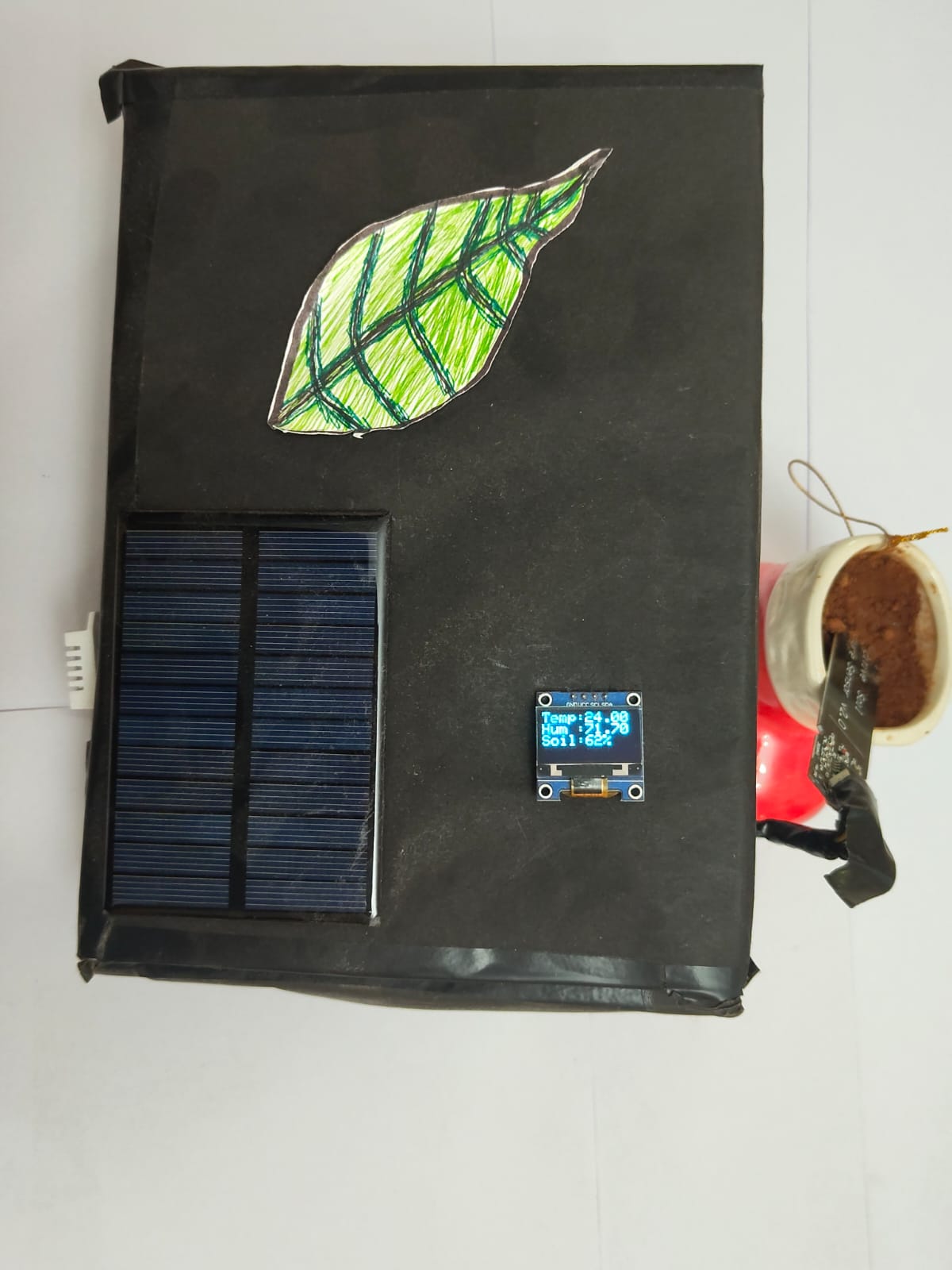
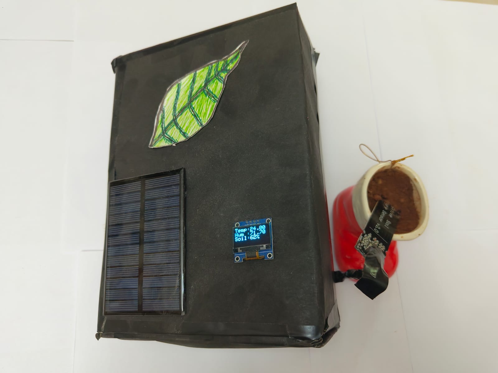
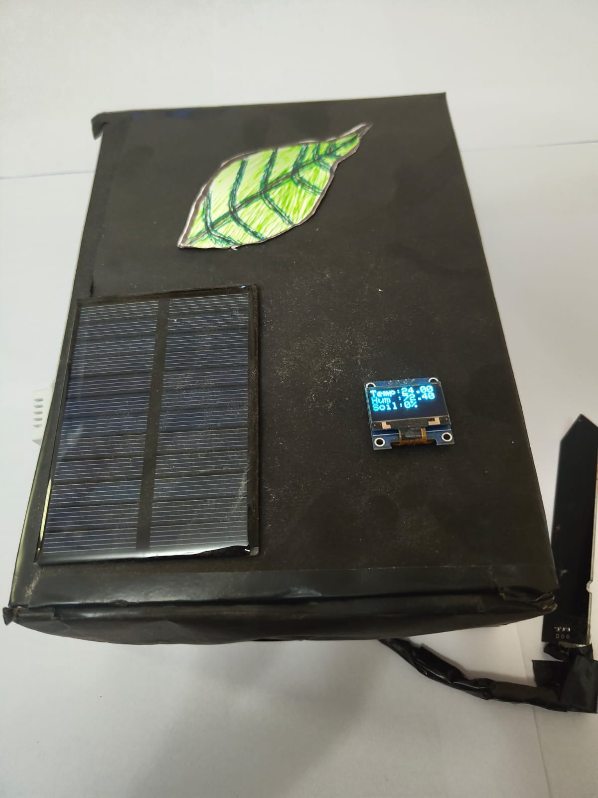
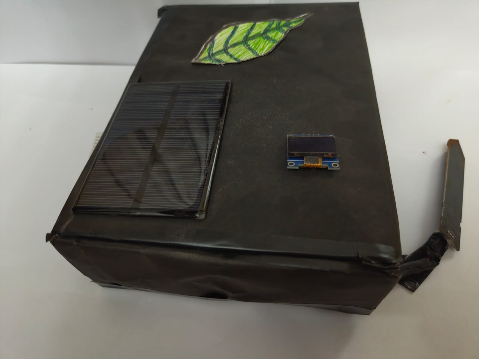
Project FarmSense — Smart Plant Monitor
A device that monitors soil and weather using only sunlight as its power source. No cables. No internet. No ongoing cost. 1st place, school computer fair. Built for ₹1,199.
When our school assigned a computer fair project, most teams built something safe and familiar. My team and I wanted to do something different — we wanted to build something that would actually be useful to a real person in a real situation, something that solved a genuine problem rather than just demonstrating a technical capability.
The question we started with was this: how do you give a farmer or a gardener useful, live information about their soil and their environment, without asking them to install a power cable, connect to the internet, or pay anything to keep it running? The answer was FarmSense. Our team built a device that reads moisture in the soil, air temperature, and humidity, displays all three live on a small screen, runs entirely on a solar panel, and costs nothing to operate after the initial setup. Total build cost across all components: ₹1,199. The team won first place at the school computer fair.
FarmSense was built with two classmates — Deepan Kishore and Ajay Krishna. Deepan took on parts of the sensor code, and Ajay contributed to the research and early planning phase. I handled the power system design, the final integration of all components, the soldering, and resolving a software conflict that was preventing the display from showing data. But what I remember most is not the division of tasks — it is the fact that we were genuinely aligned on what we were trying to make. When a team agrees on the goal from the very beginning, the work finds its own shape. That alignment is what took a school assignment and turned it into something that actually won.
The Thinking Behind It
The three constraints the team set from the beginning were non-negotiable: no mains power, no internet connection, no ongoing cost. Everything else in the design flowed from those three requirements. We did not start with what would be easy to build and work toward something useful. We started with what would be genuinely useful and worked backward to figure out how to build it.
Setting constraints first changes what you end up making. Starting from what was convenient would have produced something that plugged into a wall and sent data to a phone app — the kind of thing dozens of commercial products already do. Starting from "no power cable, no internet, no cost" forced a completely different approach and produced something that can work in a field far from any infrastructure, indefinitely, without anyone needing to manage it.
What the Device Does
FarmSense is a compact, self-contained unit. It has a sensor you push into the soil, which measures how much moisture is present. It also reads the air temperature and the relative humidity of the surrounding environment. All three of these readings are shown live on a small screen attached to the unit. The readings update continuously.
The device is powered by a small solar panel. During the day, the solar panel generates electricity and stores the surplus in a rechargeable battery inside the unit. At night, or on cloudy days, the device draws from that stored energy and keeps running. The battery system is protected in both directions — it will not be overcharged when there is excess solar power, and it will not be drained to the point of permanent damage during extended low-light periods. Both of those protections happen automatically, with no action required from the user.
Once deployed — sensor in the soil, panel facing the sun — the device runs by itself. There is nothing to maintain, nothing to charge, nothing to configure. It simply works.
The Result
Every single component in FarmSense cost ₹1,199 in total — roughly the price of a single meal at a mid-range restaurant. The project was fully functional, cleanly presented, and won first place at the school computer fair.
What FarmSense taught me, more than anything else, was what it actually feels like to build something as part of a team rather than alone. Working toward a shared goal — where every person's contribution shapes the final outcome — produces something different than working solo. The alignment we had from the very beginning, that shared clarity about what we were trying to make and why, is what turned a school assignment into something that actually won. That is a quality I intend to bring to every team I build and every business I lead.
Technical Notes — For Technical Readers [ tap to expand ]▸
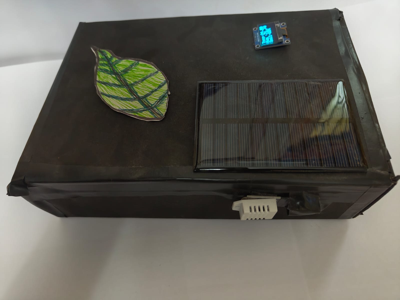
FarmSense is built around an ESP32 microcontroller reading from a DHT22 sensor for ambient temperature and relative humidity, and a capacitive probe for soil moisture. All three values display continuously on an OLED screen.
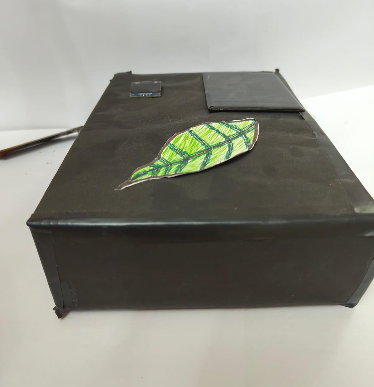
The power system is structured as a four-stage chain. A 6V 180mA solar panel feeds an LM2596S buck converter, which steps the input down to a regulated 5V. This output drives a TP4056 lithium-ion charging module, which manages charge delivery to an 18650 cell rated at 2200mAh, enforcing an upper cutoff at approximately 4.2V and disconnecting the load under low-voltage conditions to prevent deep discharge. Downstream of the cell, an MT3608 boost converter produces a stable 5V rail for the ESP32 and all peripherals. Structuring the chain this way keeps each stage isolated, preventing voltage noise from propagating between stages. Total component cost was ₹1,199. The enclosure is custom cardboard with a hand-drawn leaf graphic on the top panel.
Self-FundedAviationAge 156 Months
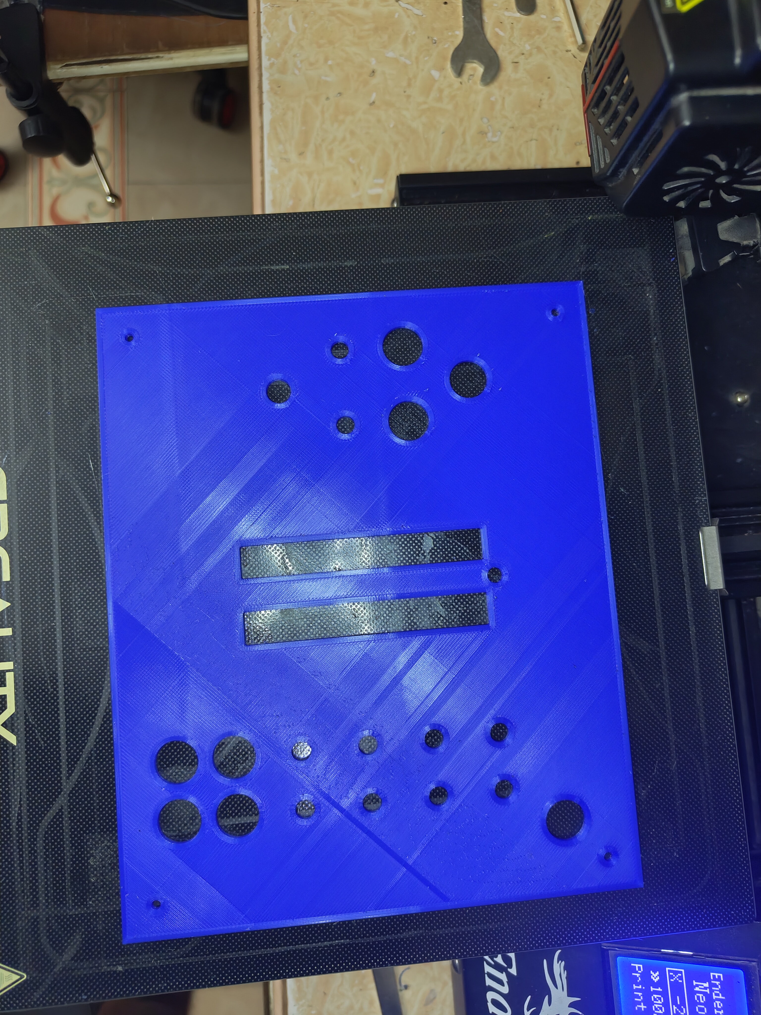
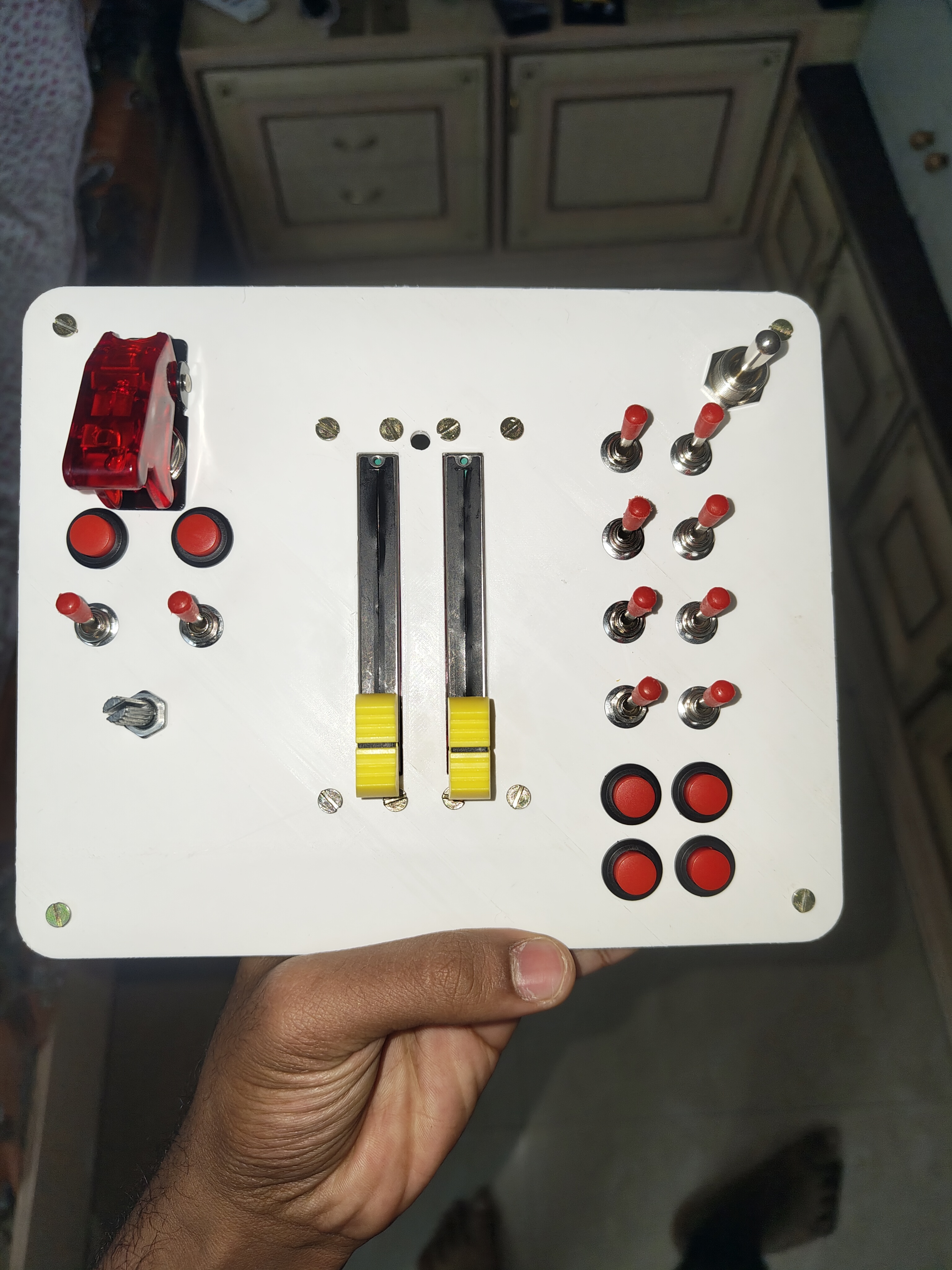
Project HOTAS — Throttle Quadrant
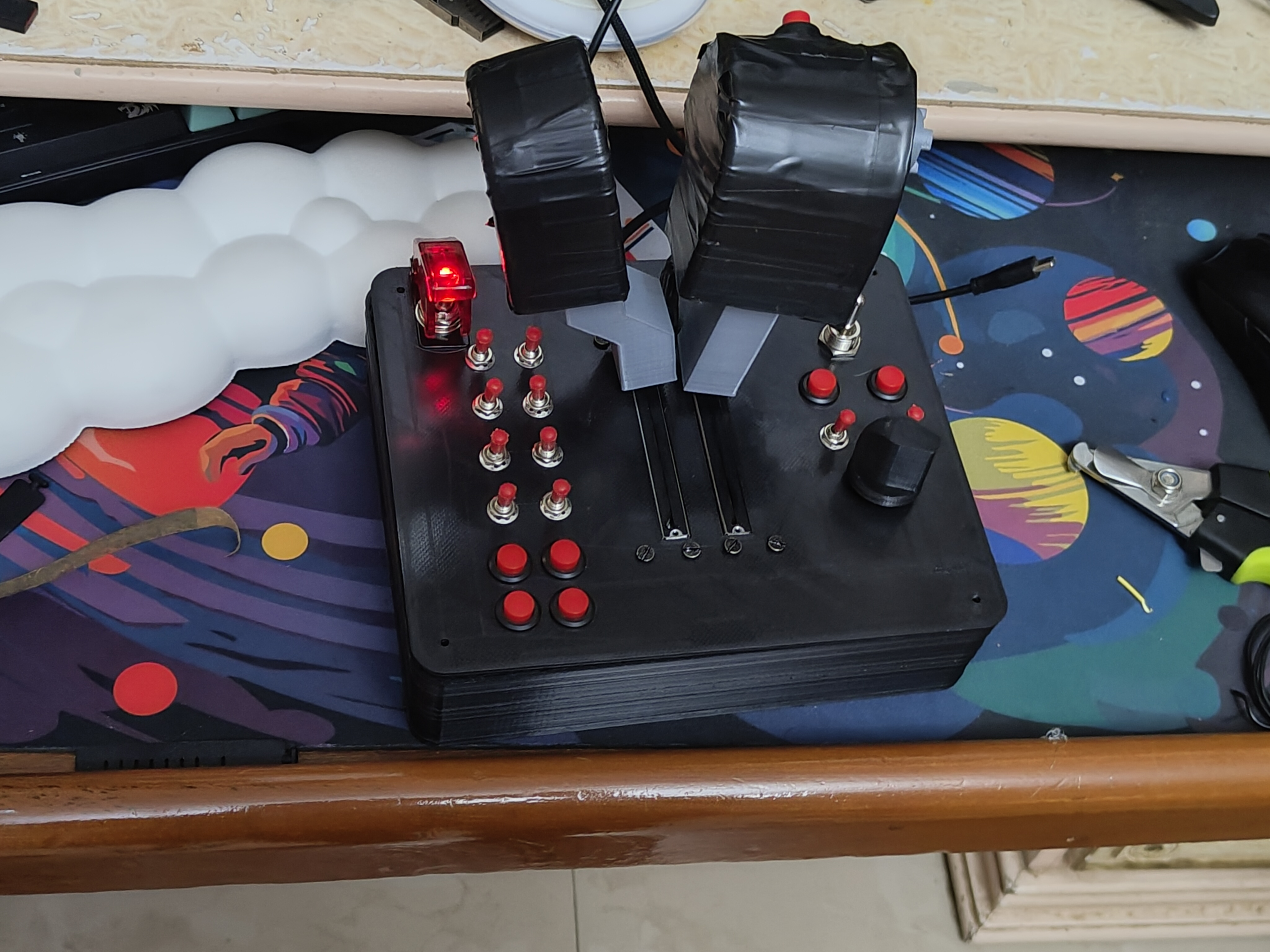
Built from scratch after the commercial option cost too much. Six months. Twenty-eight redesigns. One working result.
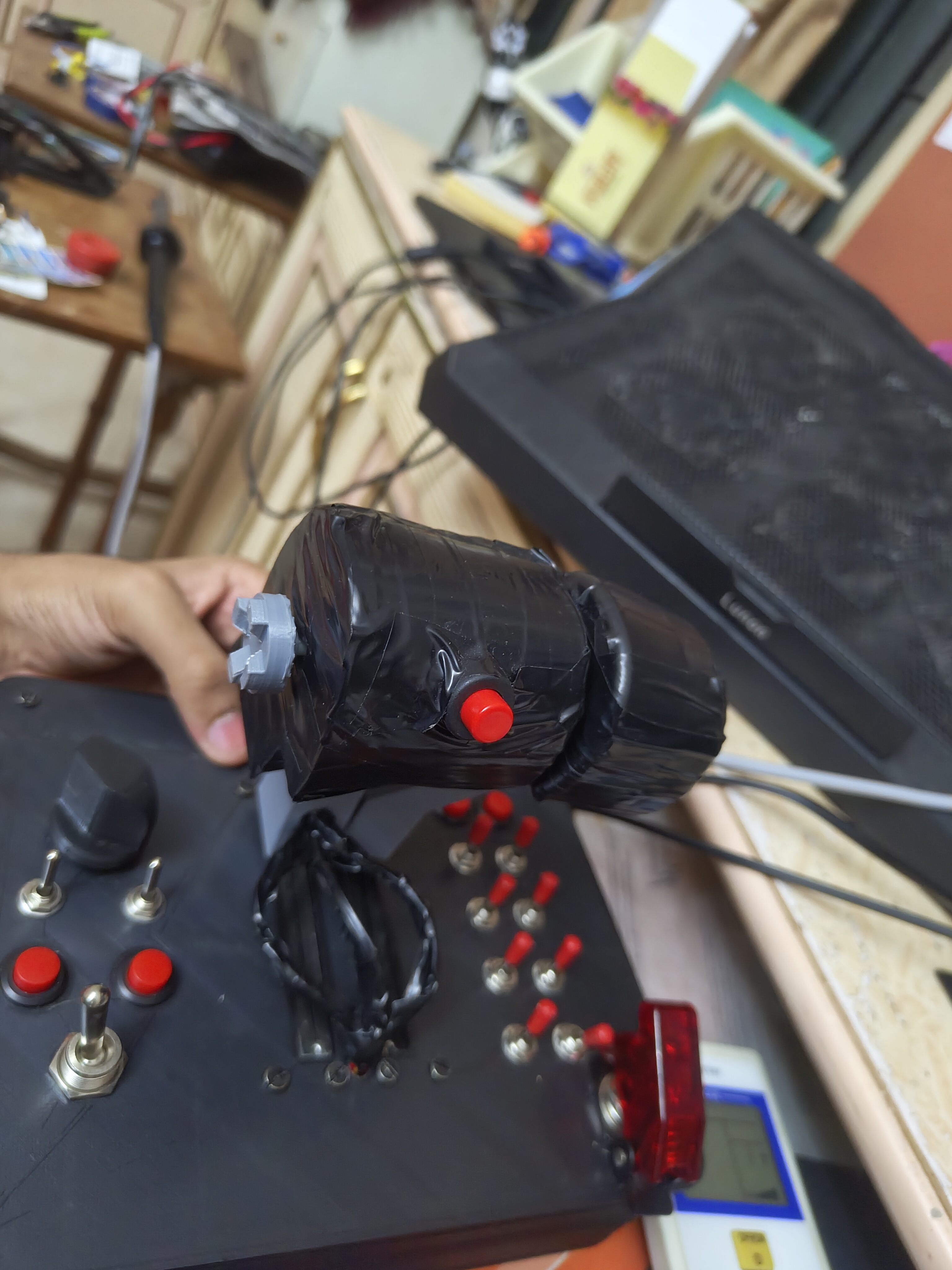
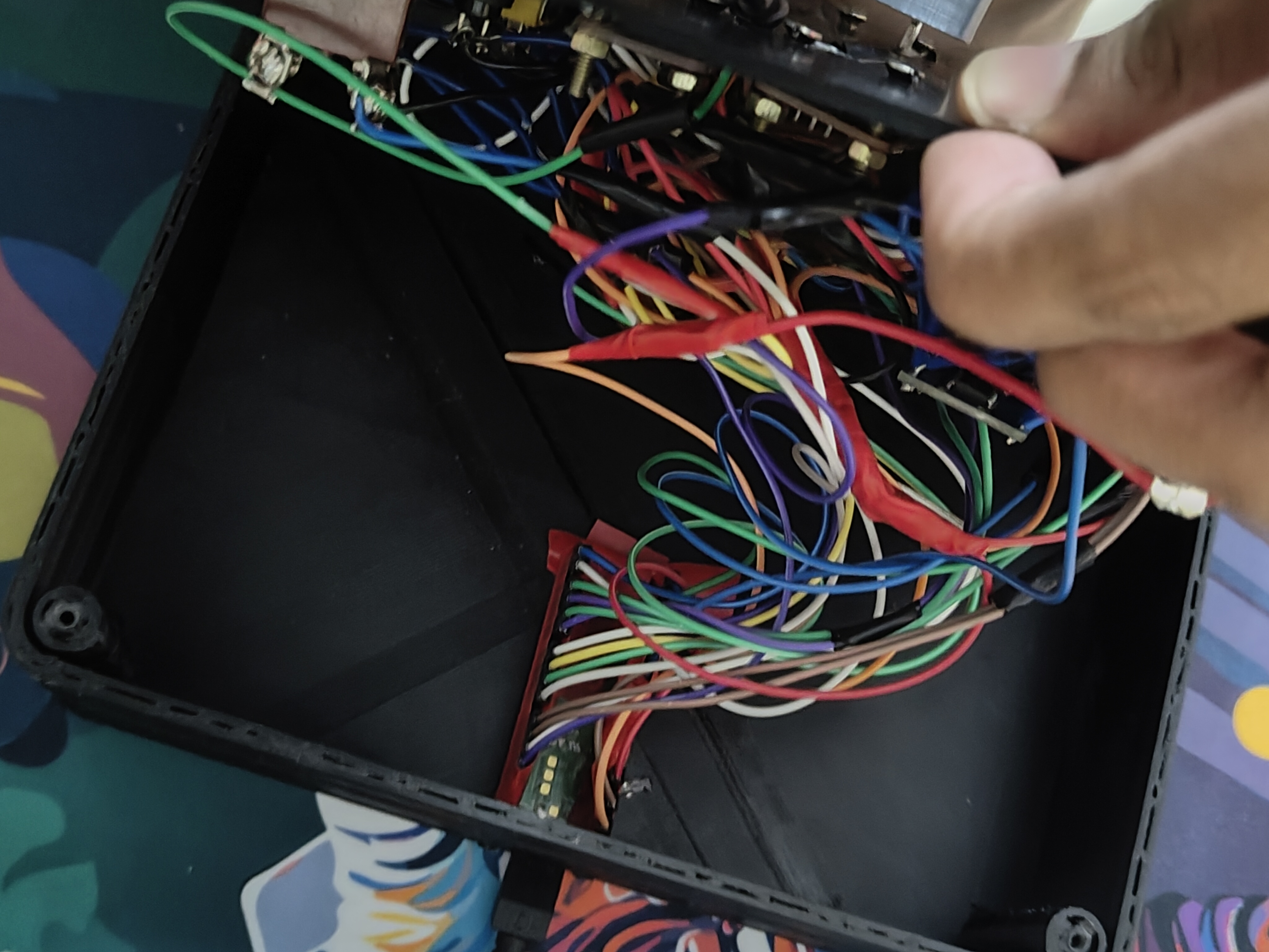
I fly a military-grade flight simulator called DCS World — think of it as the most realistic aircraft simulation available to the public outside an actual cockpit. For a long time, I had a frustrating problem: both engines on my twin-engine aircraft were controlled by a single lever on my joystick. In combat, when one engine took damage, I had no way to manage the two independently. I needed a dedicated controller with two separate levers — one for each engine — so that even a damaged aircraft could be kept in the air.
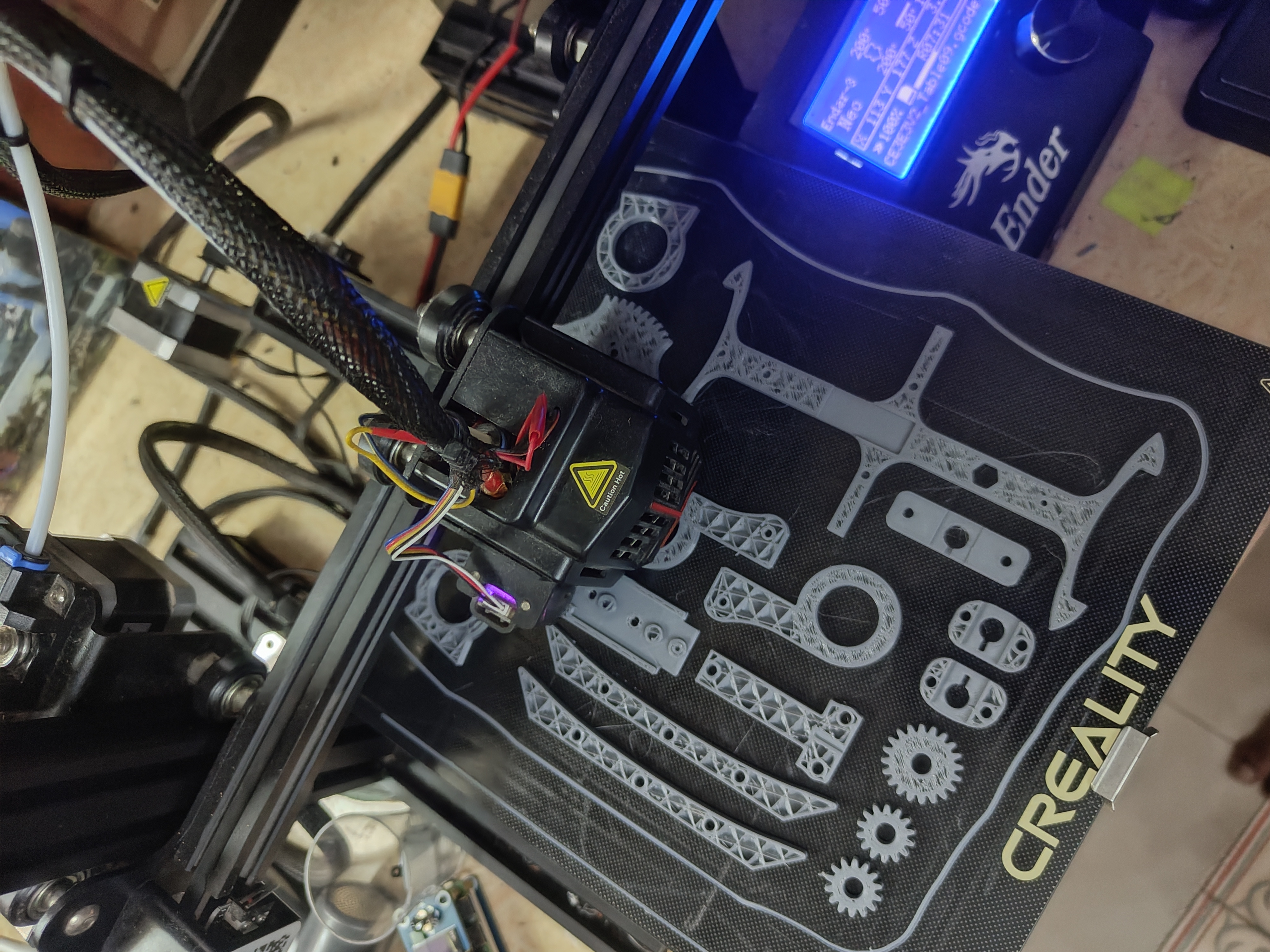
The hardware I needed starts at around ₹25,000 from commercial brands. At fifteen years old, with no engineering background and no formal training of any kind, I decided to build one from scratch instead. What followed was six months of designing, printing, testing, failing, and redesigning — and what came out the other side taught me about resilience in a way I strive to bring to everything I do.
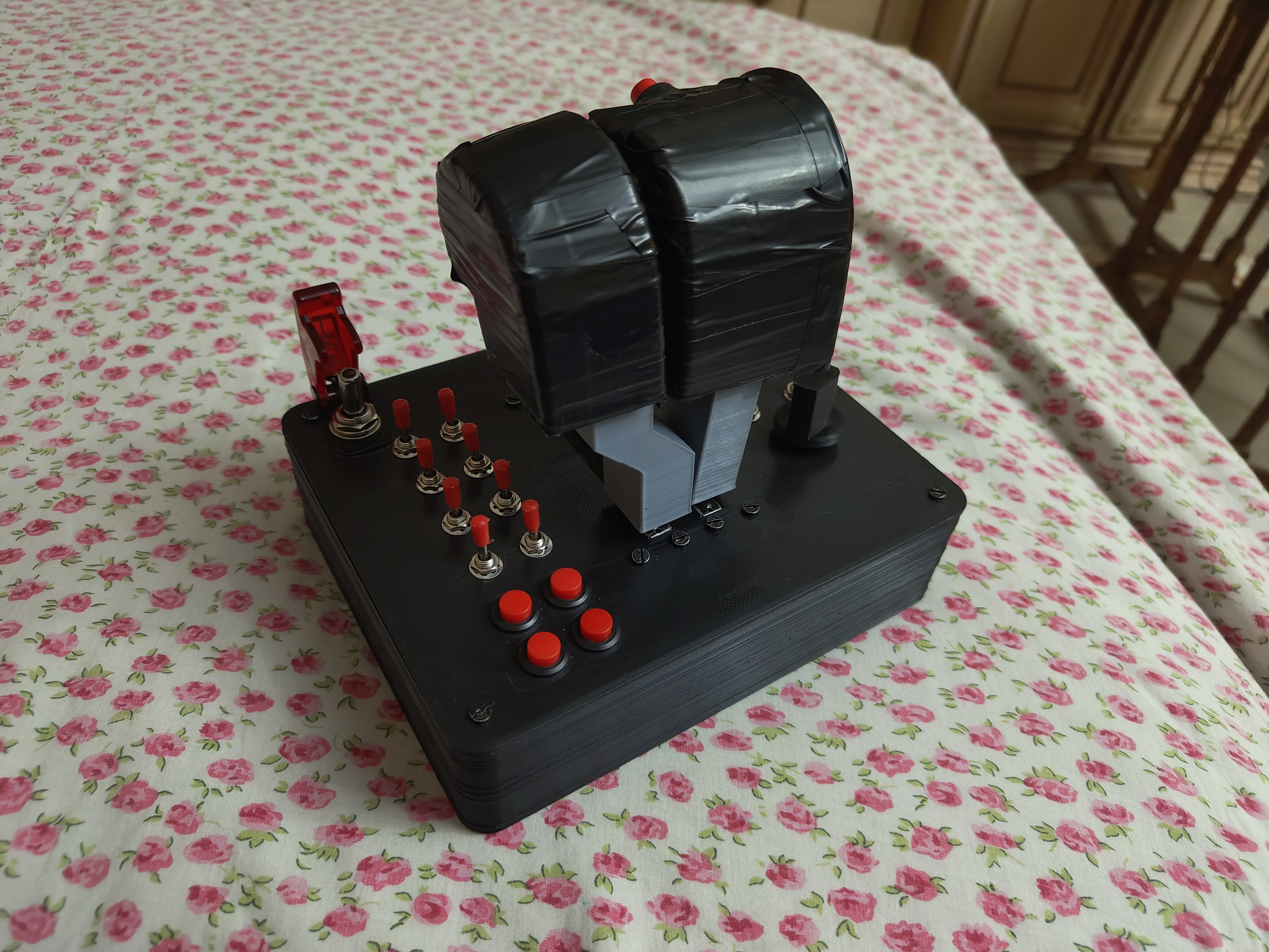
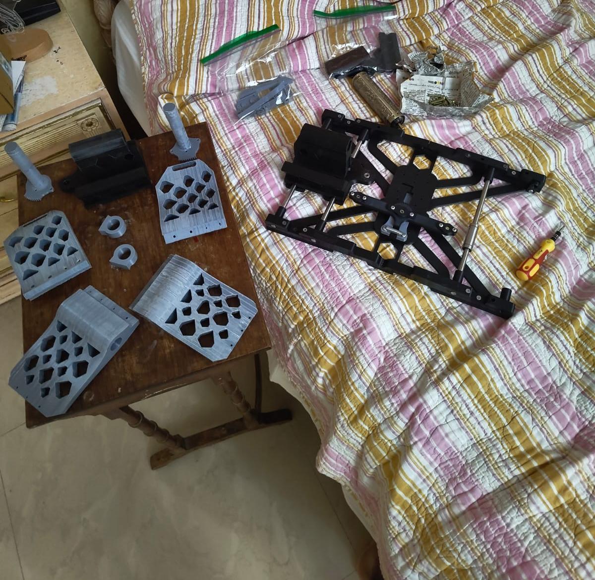
Completed HOTAS — front view, both throttle handles in position
Where It Began
I remember the exact moment the project started. I was studying when a notification appeared on my phone showing a component I had never seen before — a sliding potentiometer. It is a simple part: you slide it back and forth, and the device connected to it reads how far along the slider is. The moment I saw it, I realised that two of these, placed side by side, could act as two completely independent engine levers. A few toggle switches would become buttons. The entire controller I needed could theoretically be built from individual parts for a fraction of what brands were charging.
I added the components to my cart, finished my studying, and the project had begun.
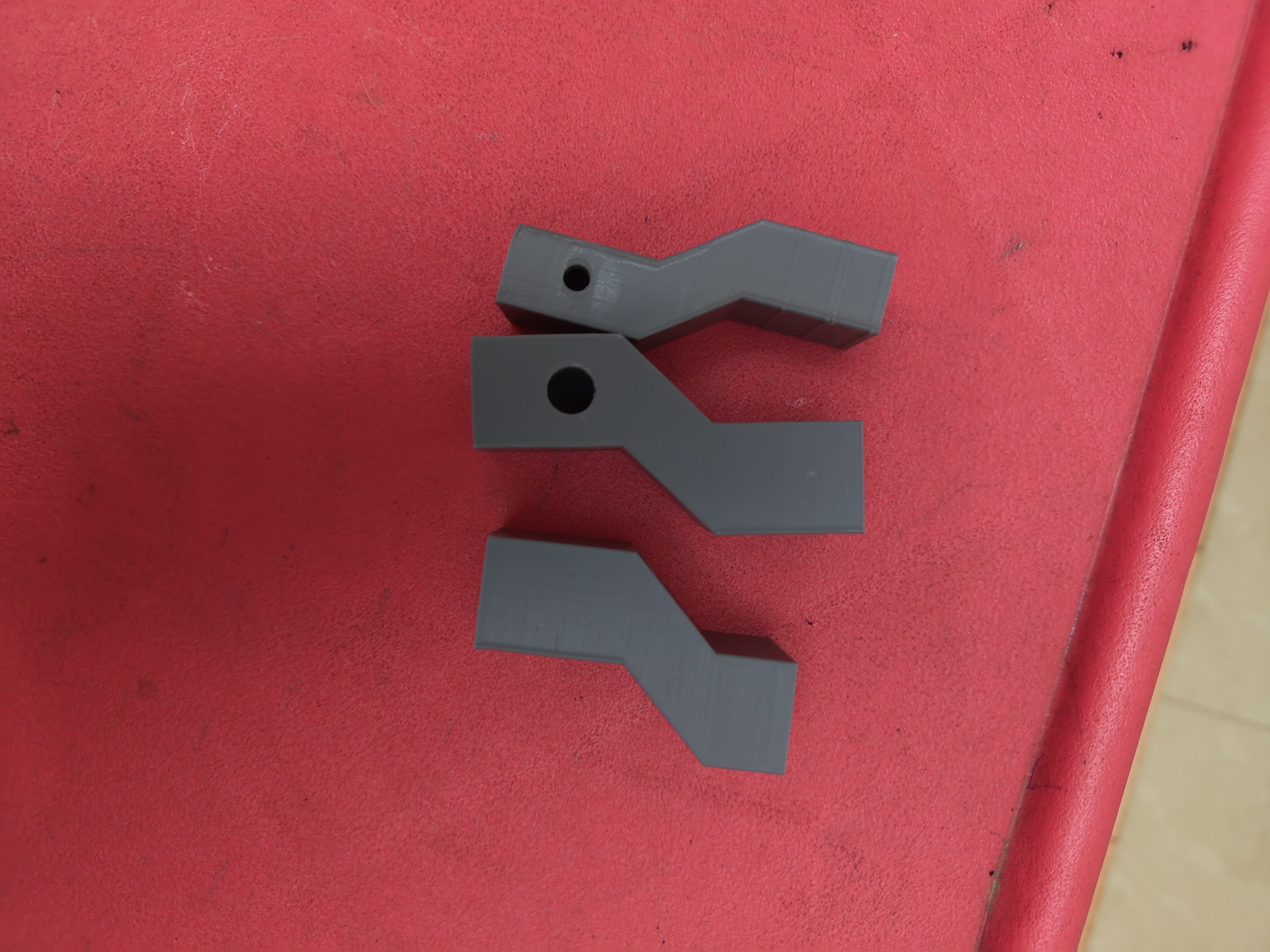
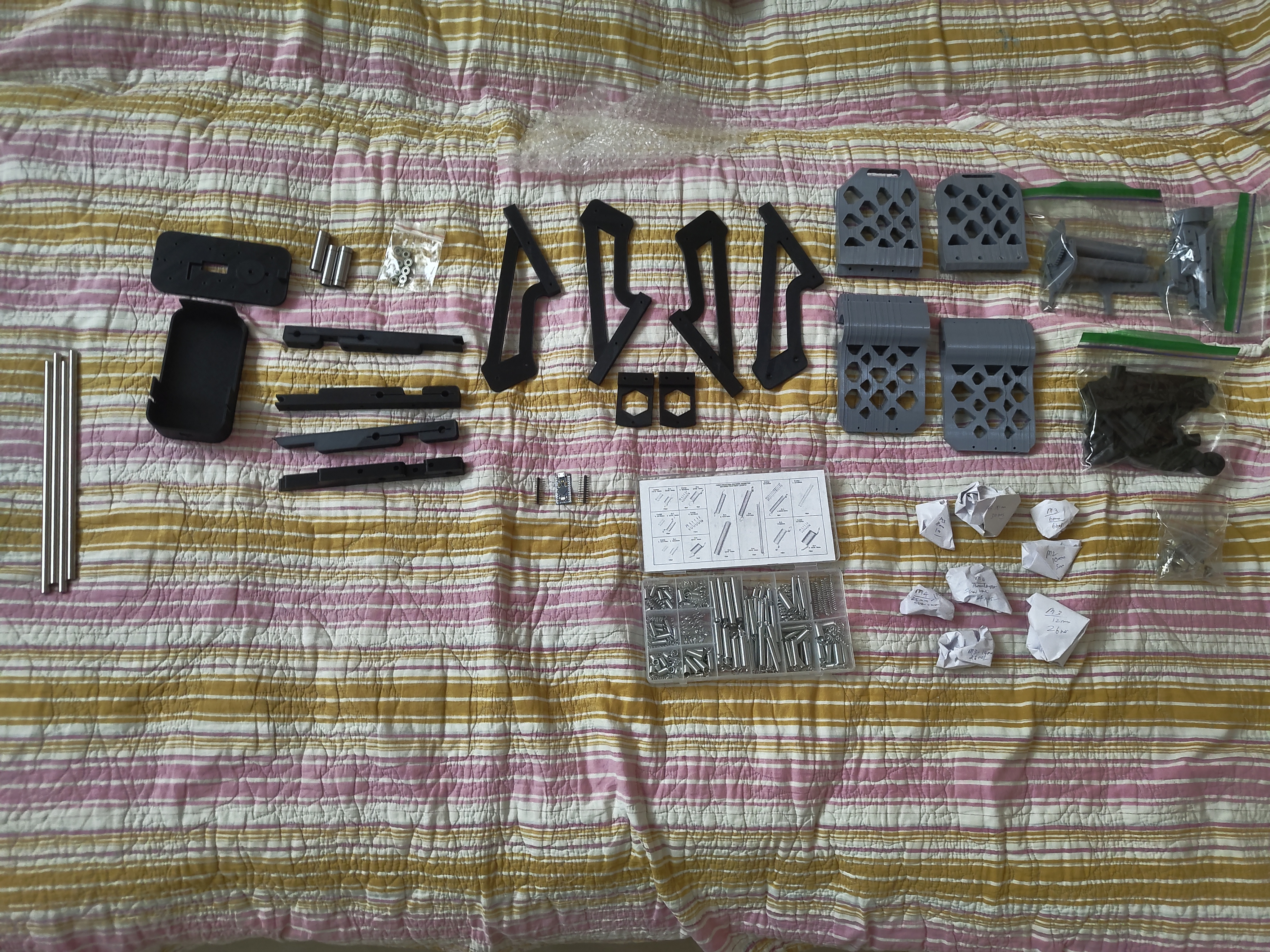
Twenty-Eight Redesigns
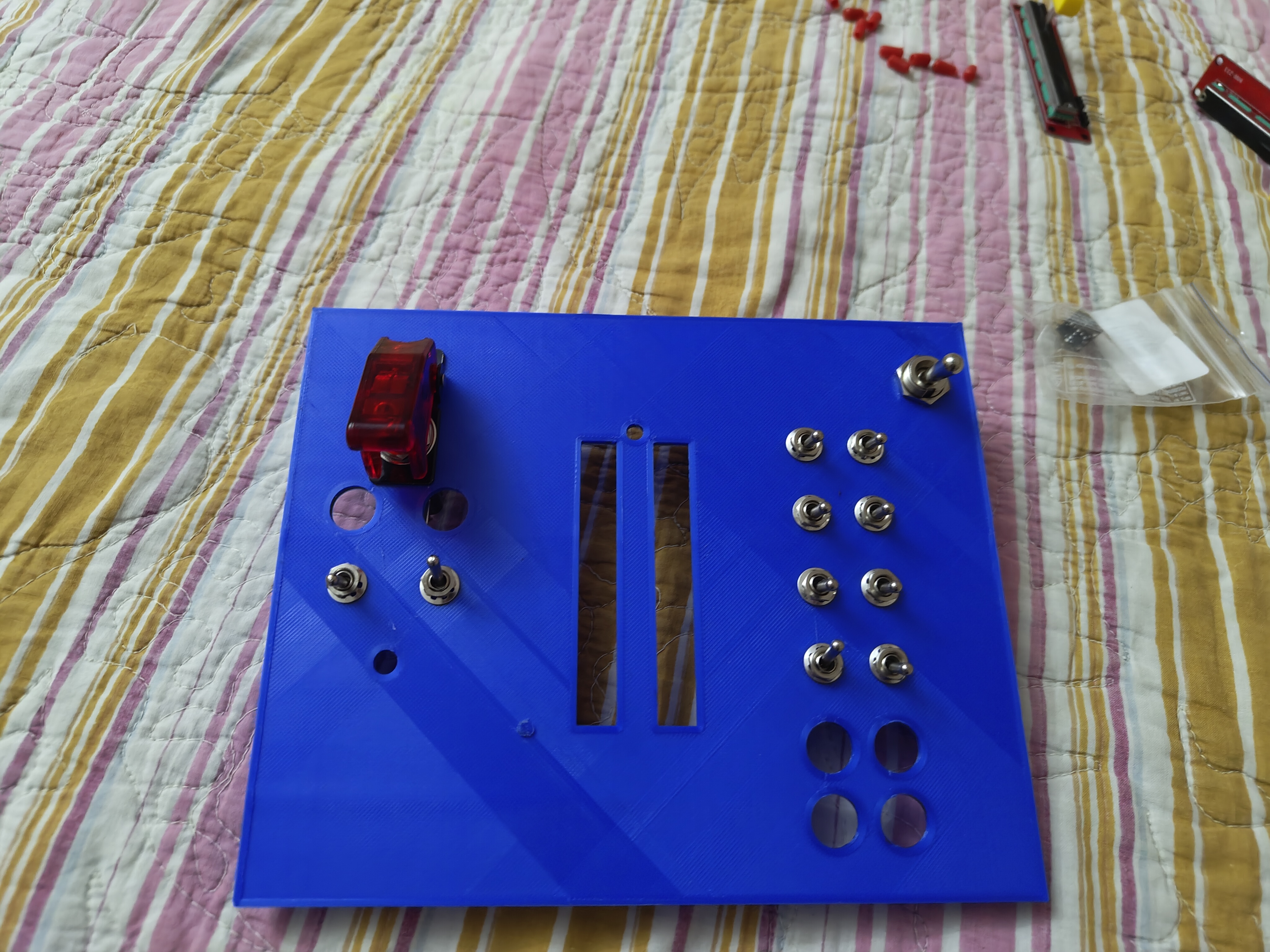
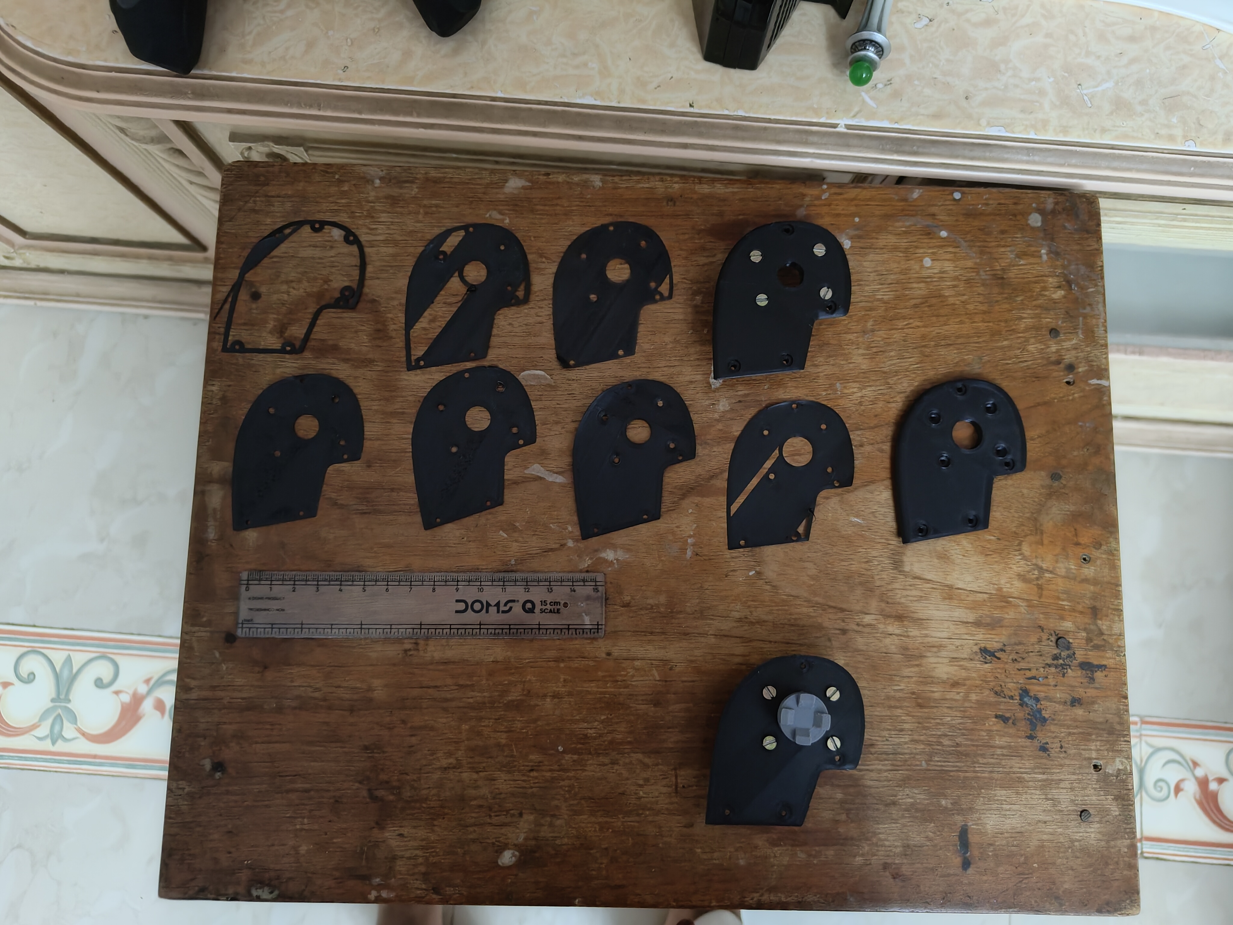
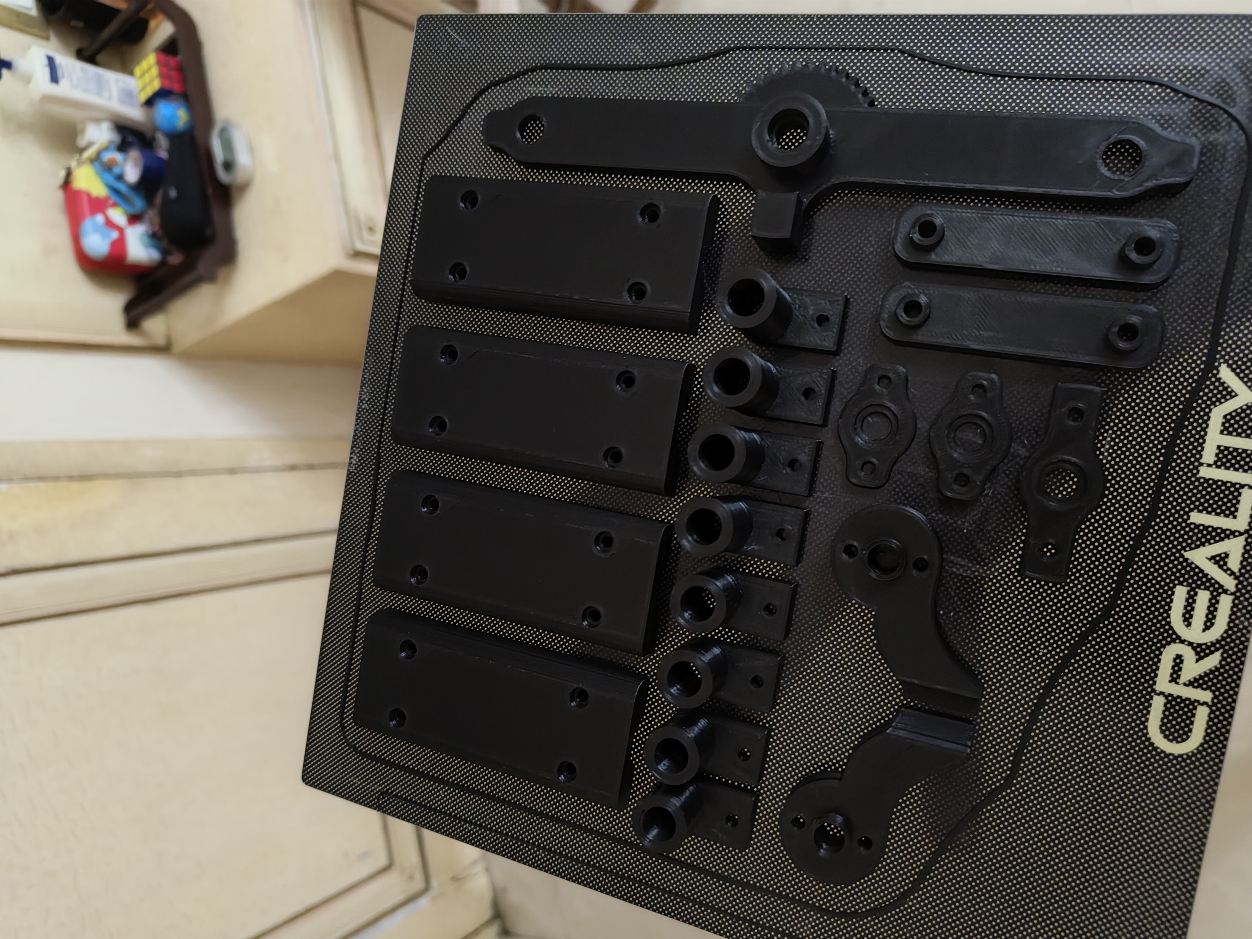
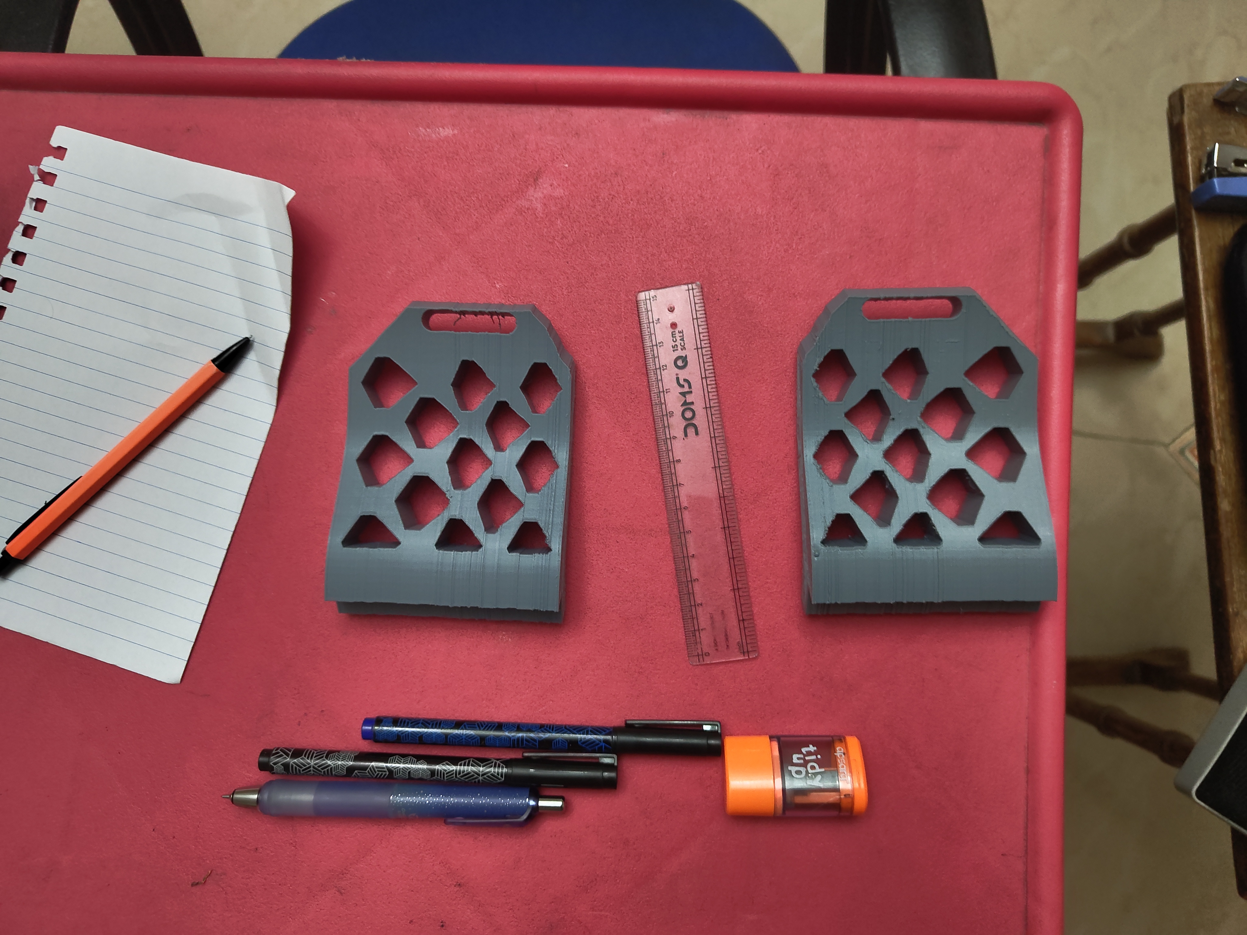
The most time-consuming part of the entire project was designing the casing — the physical housing that holds all the buttons, switches, and levers in place. I had no prior experience designing objects in three dimensions, so I learned entirely by doing: designing something, printing it, finding all the things that were wrong, and starting again.
I went through twenty-eight major versions of the main casing. Many of those versions had multiple sub-versions — small adjustments that each got their own print and test — before being replaced entirely by the next major version. The version numbering started over at version one each time a design changed fundamentally enough to warrant it, and some sub-versions counted up to 0.9 before the next major reset. It was a long process.
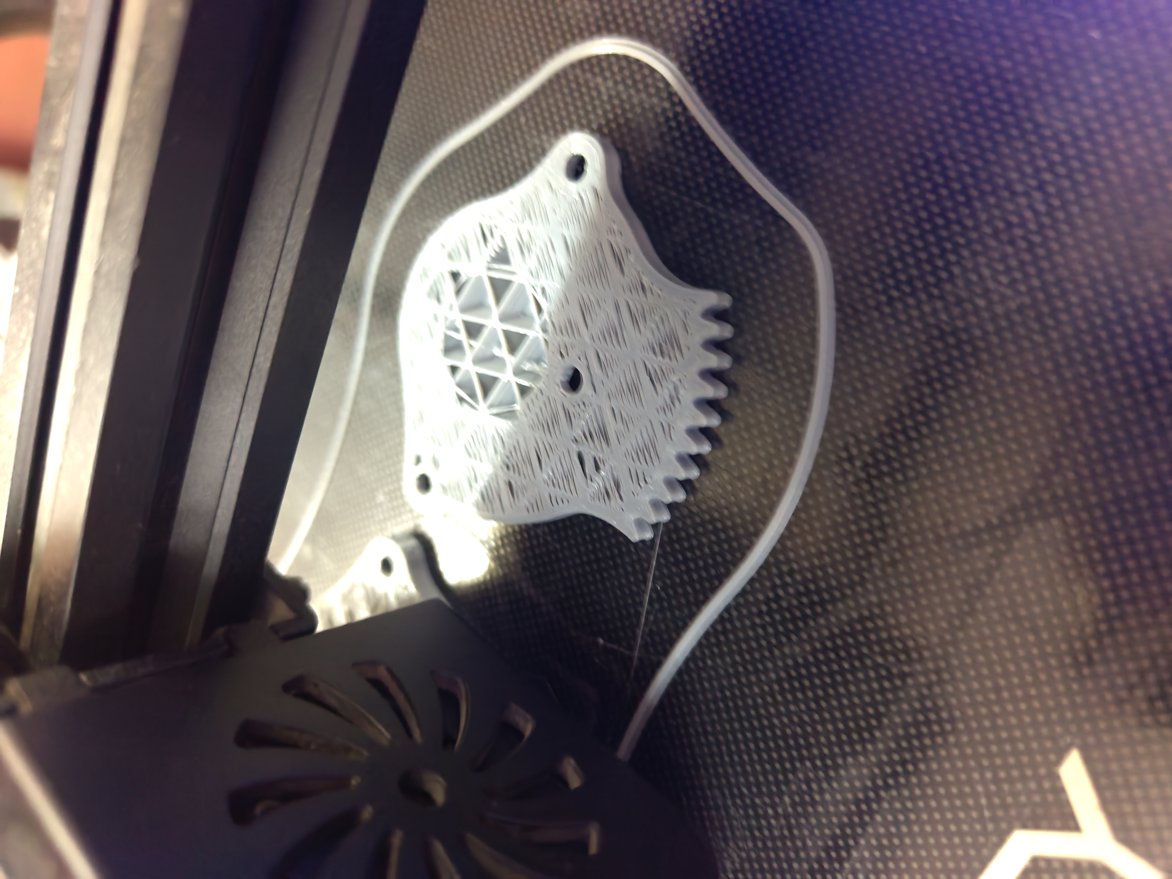
The key insight that made all of this manageable was realising I did not need to print the full casing each time to check whether measurements were correct. A complete print took seventeen hours. But the critical holes and mounting points all sit at the bottom of the design — which meant printing just the first few layers, which took around twenty minutes, was enough to check whether everything was in the right position. I could find a problem, fix it, and test again all within the same evening. That one realisation compressed what would have been a months-long process of waiting into something I could iterate through quickly.
Problems Solved Along the Way
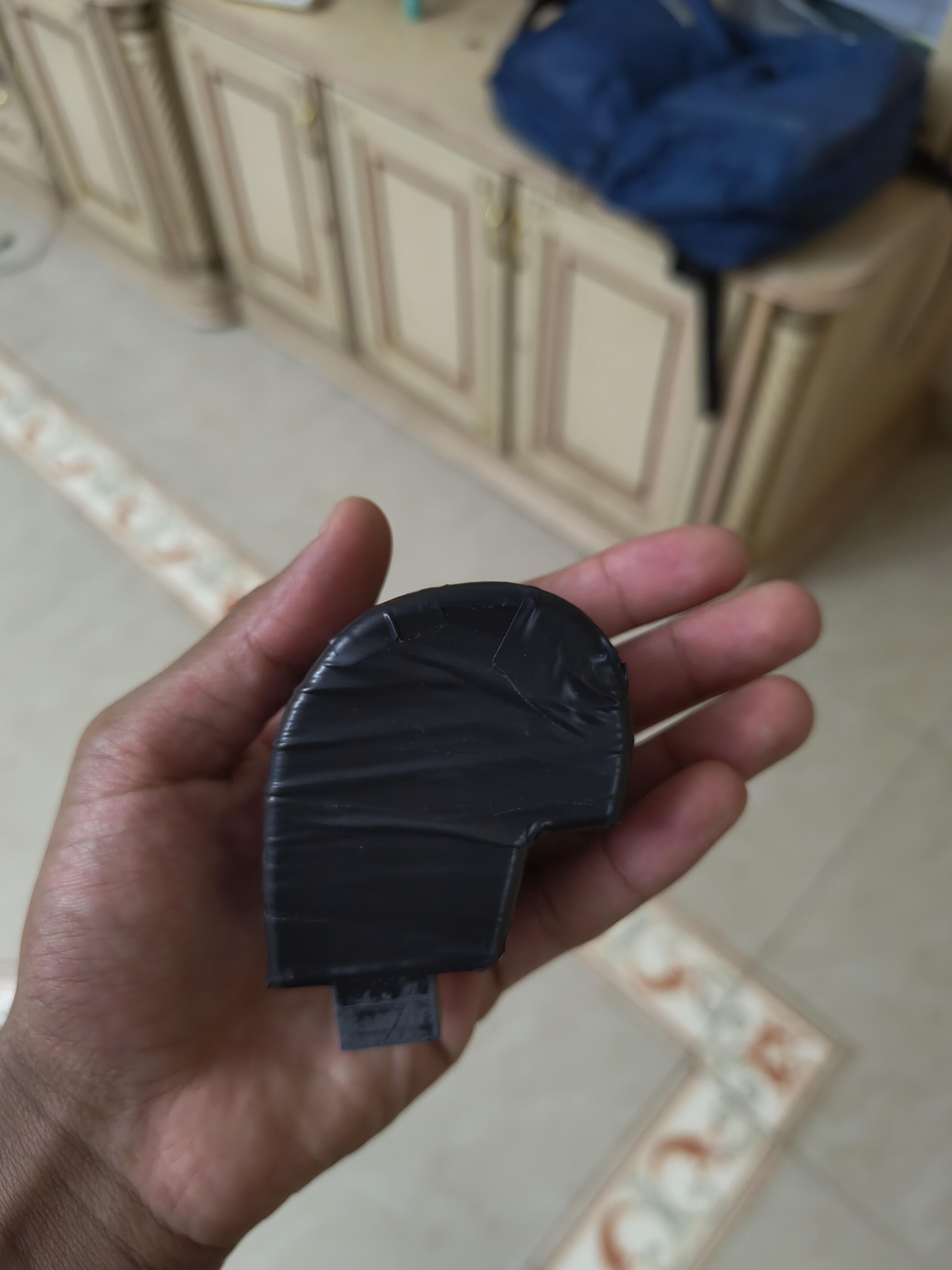
My 3D printer had a persistent issue throughout this project: it consistently printed holes slightly smaller than the design specified. Screws and components that should have fit did not. I worked through this in two ways. For holes that were close to the right size, I enlarged them manually using a drill I had improvised from an old electric hair trimmer with a thin blade attachment. For more significant mismatches, I redesigned specific parts to account for the printer's consistent offset rather than fighting it every time.
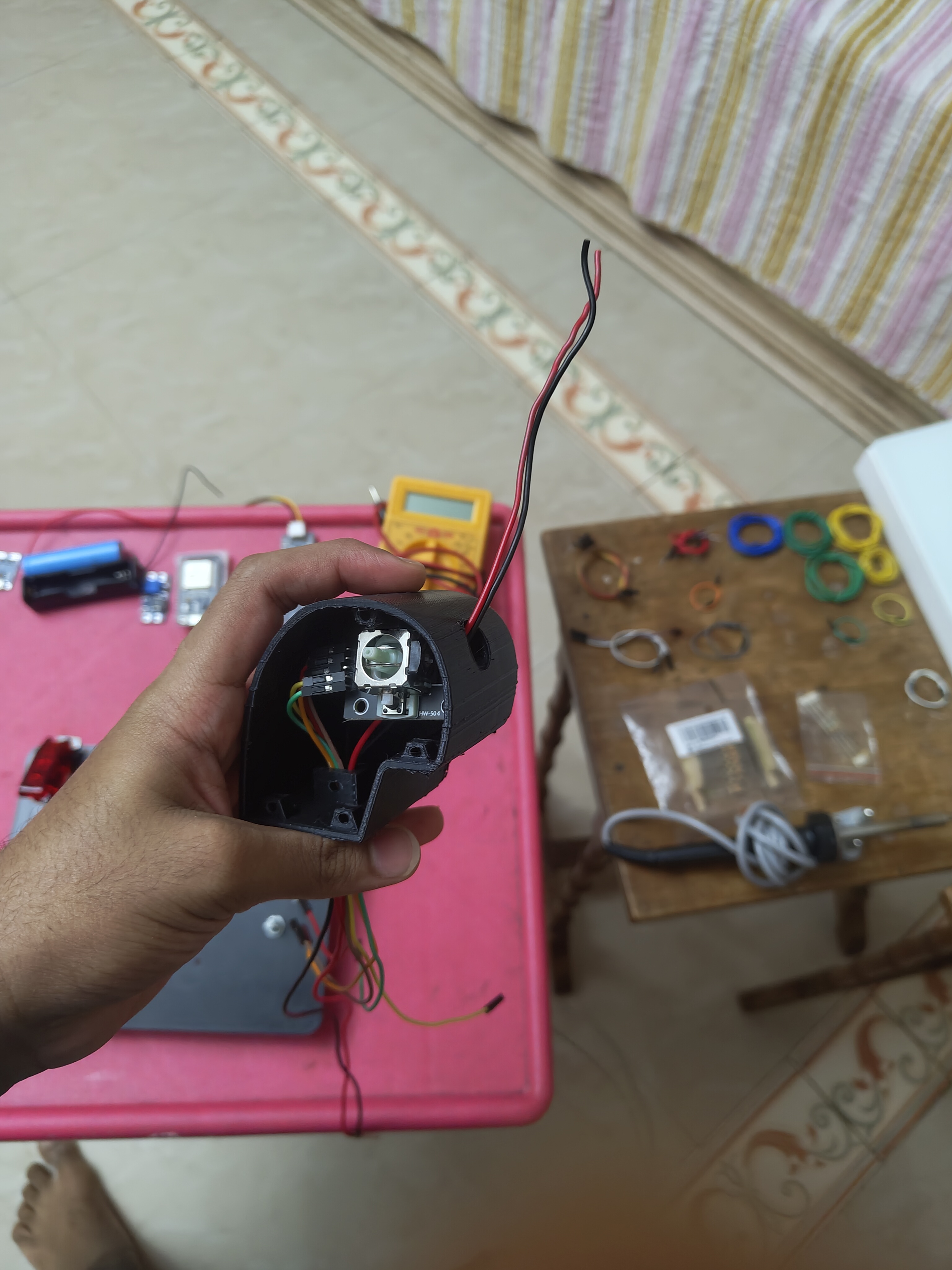
I also built something into the controller's software that I am particularly proud of. If you flip one specific switch on the controller before plugging it in, the device changes its behaviour entirely: instead of appearing on the computer as a game controller, it appears as an editable storage drive. This means I can update settings, adjust sensitivity, and change any part of the configuration without ever opening the hardware and without needing any special tools. It was a small design decision, but it made ongoing development and maintenance dramatically cleaner.
Later in the build, I noticed that the wiring running from one of the handles was starting to show signs of stress. Every time I moved the throttle to full power and back, the same point in the wire was bending sharply. If I had left it, the wire would eventually have broken at that point. Instead, I redesigned the way the wires were routed so that the tension was spread across three separate sections rather than concentrated at one. I worked that solution out entirely on my own, without looking anything up. The wiring has been running without issue ever since.
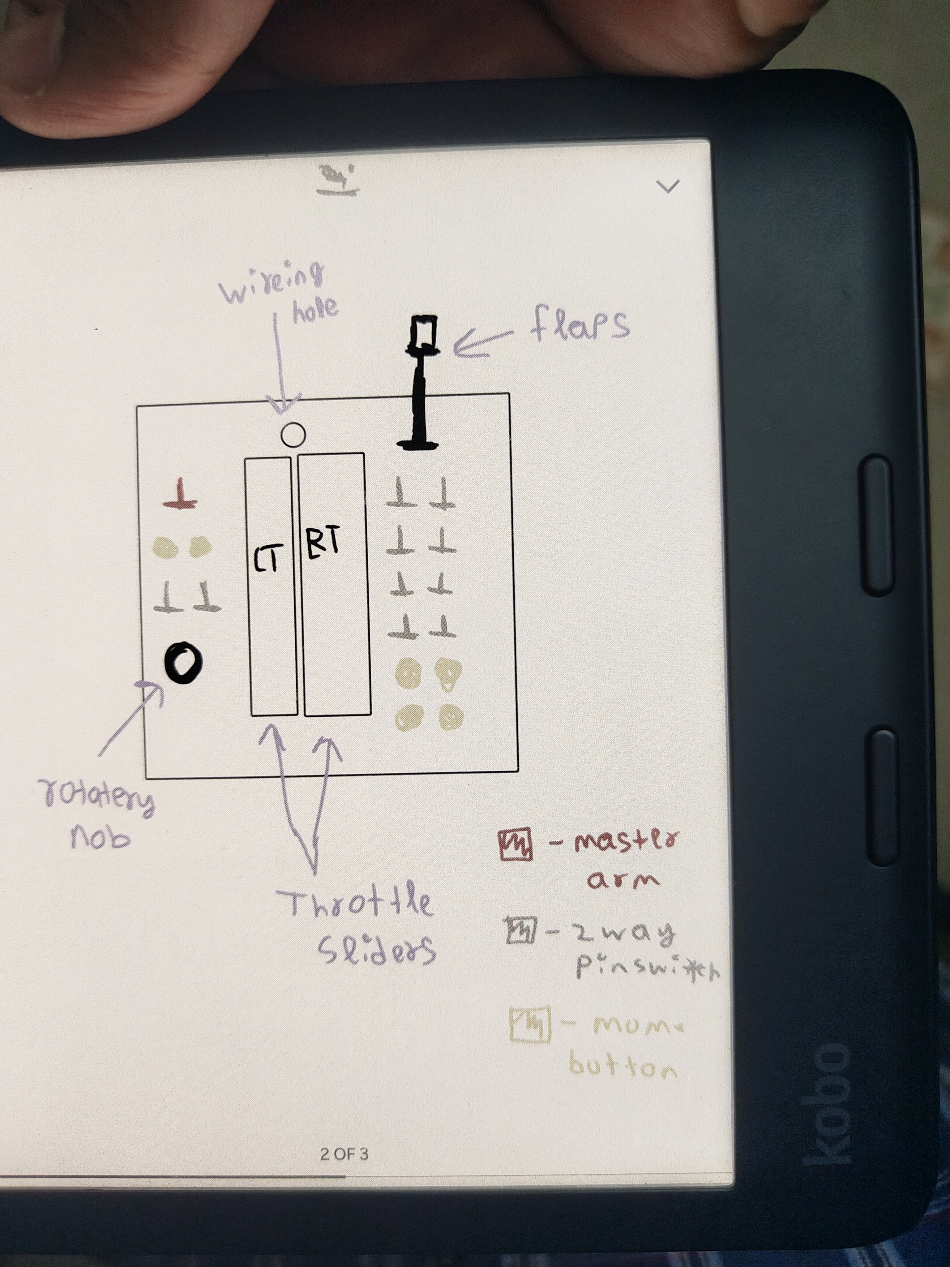
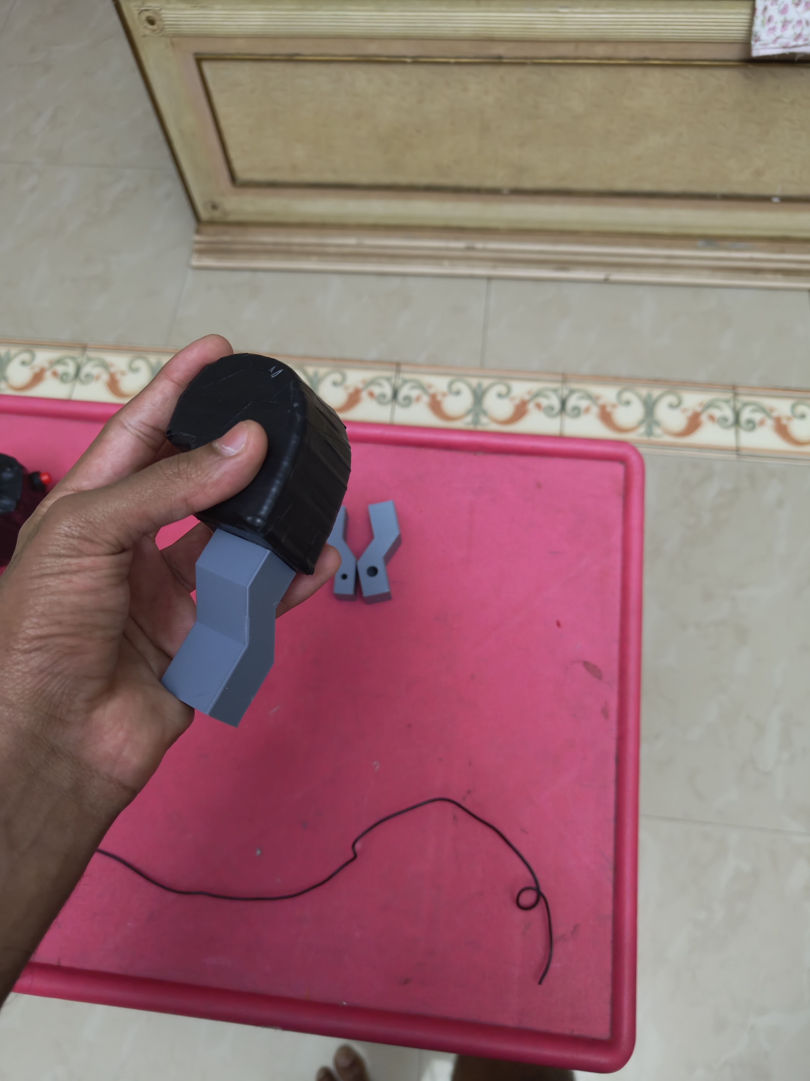
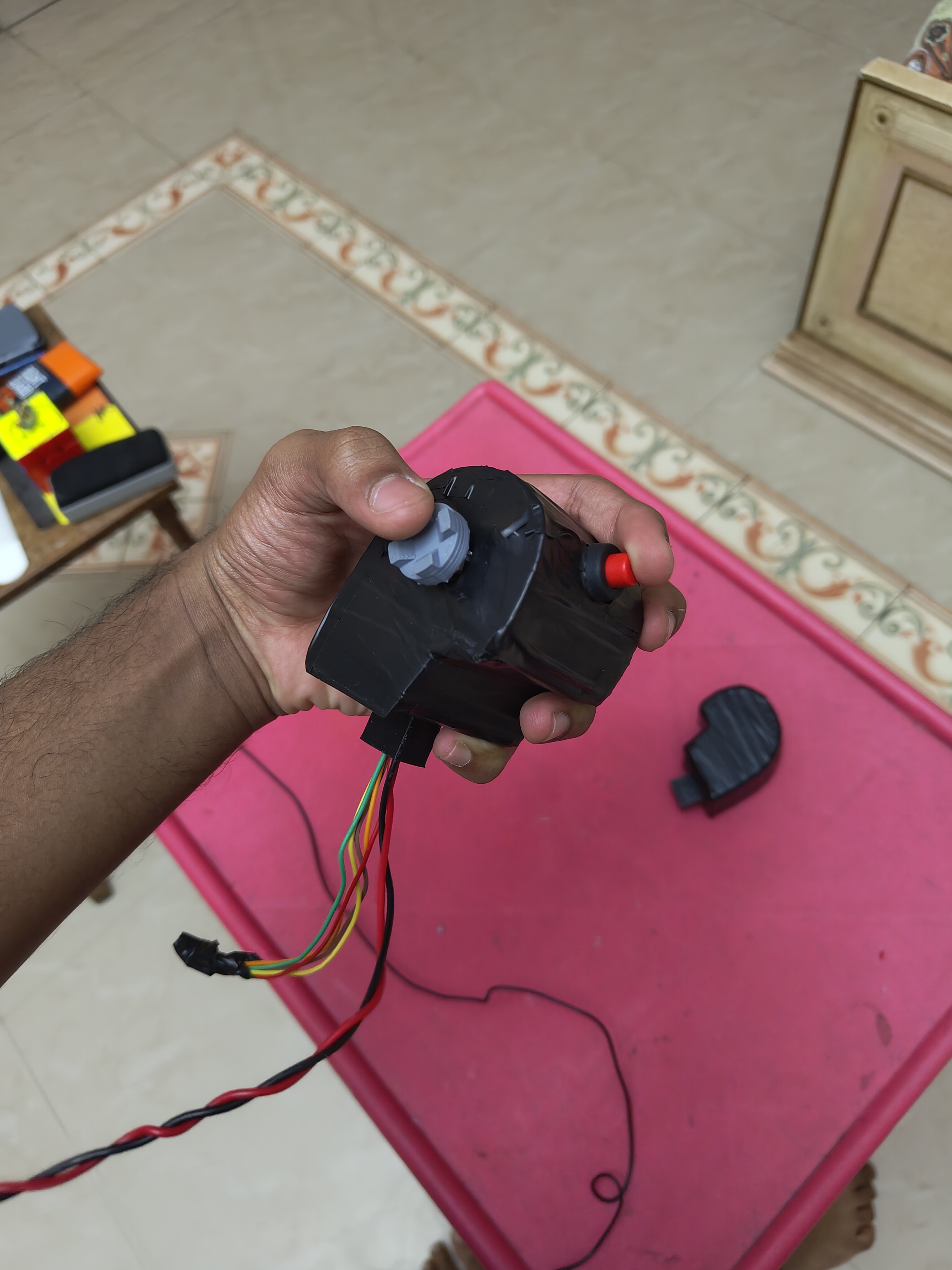
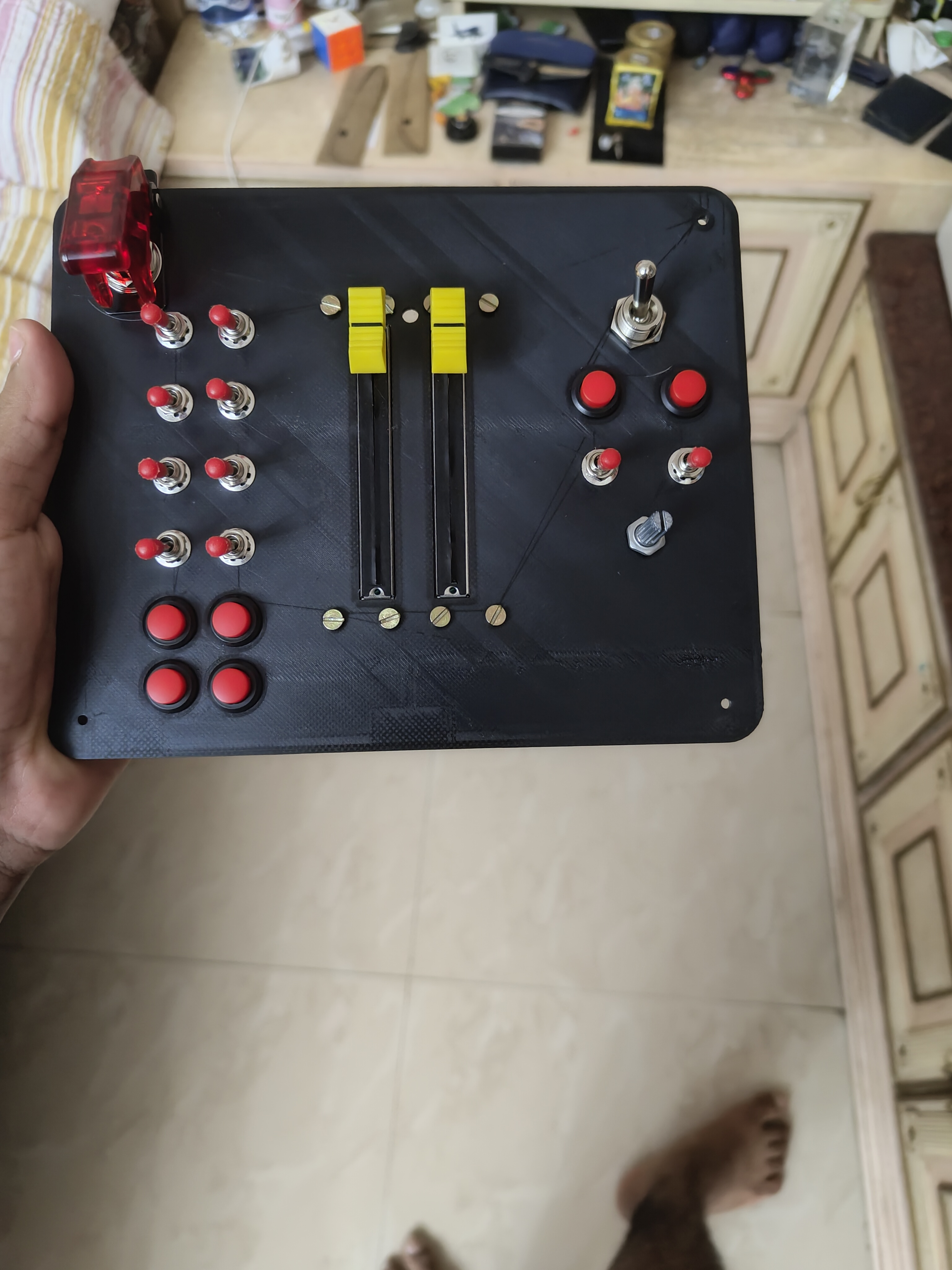
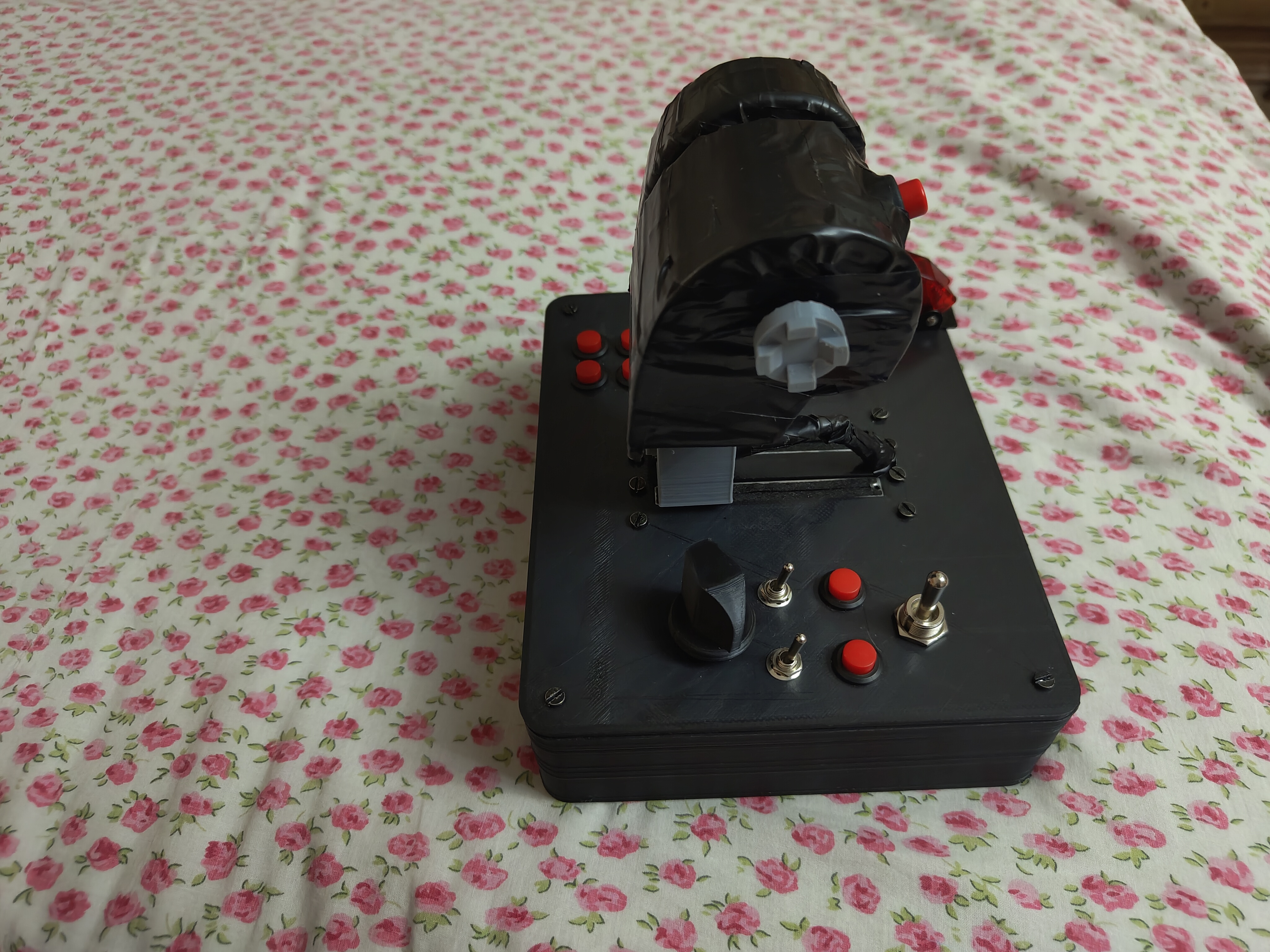
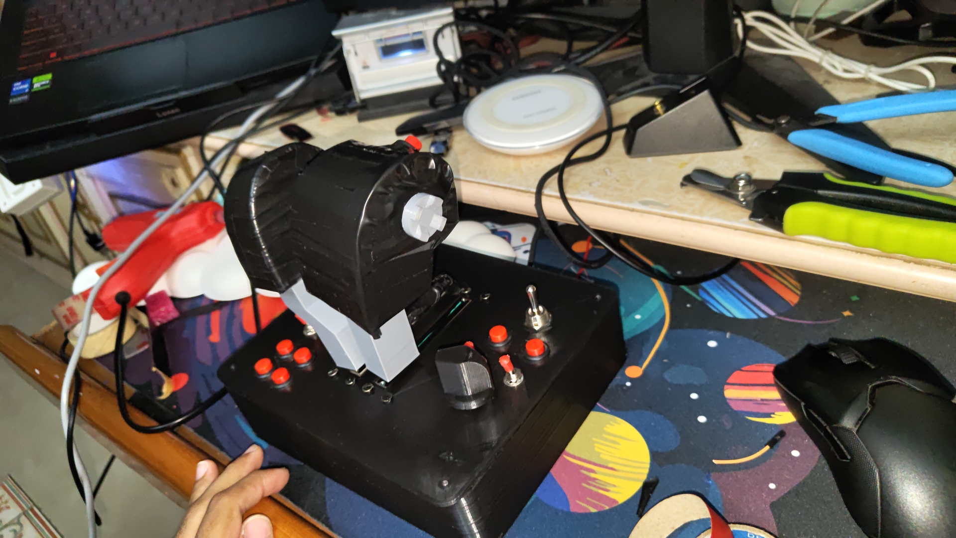
The Finished Result
The finished controller has two fully independent engine levers, ten switches and buttons across the base and the handles, a small joystick on the right handle for fine control inputs, a rotary dial for mixture control on older aircraft types, and the master arm switch that doubles as the boot-mode selector I described. The whole thing runs on a small microcontroller that I programmed myself.
Every component that wears out from regular use — the sliding potentiometers, primarily, which I have already replaced three to four times — can be swapped in under five minutes, without soldering and without any special tools. That was a deliberate design decision I made from the beginning: the controller had to be maintainable long-term without becoming a complicated repair job. I funded the entire build personally and completed it at fifteen years old, while keeping up with all academic commitments.
What I Took From It
This project changed the way I see problems. Before it, I was a consumer of technology — someone who used things other people had built. After it, I understood that almost anything can be made by someone willing to iterate past the point where most people give up. The gap between an overpriced solution and no solution at all is not a dead end. It is exactly where the most interesting work happens.
That is the insight I want to bring to every business I build. Find where the market is wrong — overpriced, poorly designed, or simply absent — ask whether you can build something better, and keep going until you can.
Technical Notes — For Technical Readers [ tap to expand ]▸
The controller is built around a Raspberry Pi Pico running MicroPython, presenting to the host PC as a USB HID joystick device. Analog inputs are handled by an MCP3008 eight-channel SPI analog-to-digital converter. The left and right throttle sliders connect to channels 3 and 4 respectively, a rotary potentiometer to channel 2, and the thumbstick TDC slew axis to channel 6. The SPI bus runs on GP10 through GP13.
Digital switch inputs are managed through a PCF8575 sixteen-bit I²C GPIO expander, which allows all toggle switches to share a two-wire bus. Each three-position ON-OFF-ON toggle is wired with its common terminal to ground and its UP and DOWN terminals to separate PCF pins. The firmware reads the full sixteen-bit register over I²C and extracts each switch state by isolating the relevant bits. Make-before-break contact behaviour during switching is handled by a state machine that holds the last valid state through any transient condition. The I²C bus runs on GP4 and GP5.
Additional inputs connect directly to GPIO: the illuminated Master Arm switch on GP2, a three-way flap selector across GP3 and GP6, four toggle switches, six push buttons, and the thumbstick push-click on GP21. The split-throttle detent uses a pair of neodymium magnets. Boot mode is determined by Master Arm switch position at power-on: the raised position (on, high state) initialises USB mass storage for firmware access; the lowered position (off, low state) initialises HID joystick mode. All systems are fully operational.
Self-FundedAviationAge 15–16
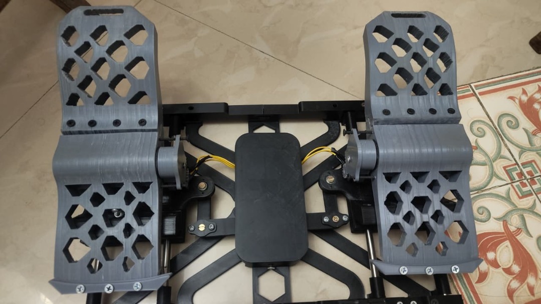
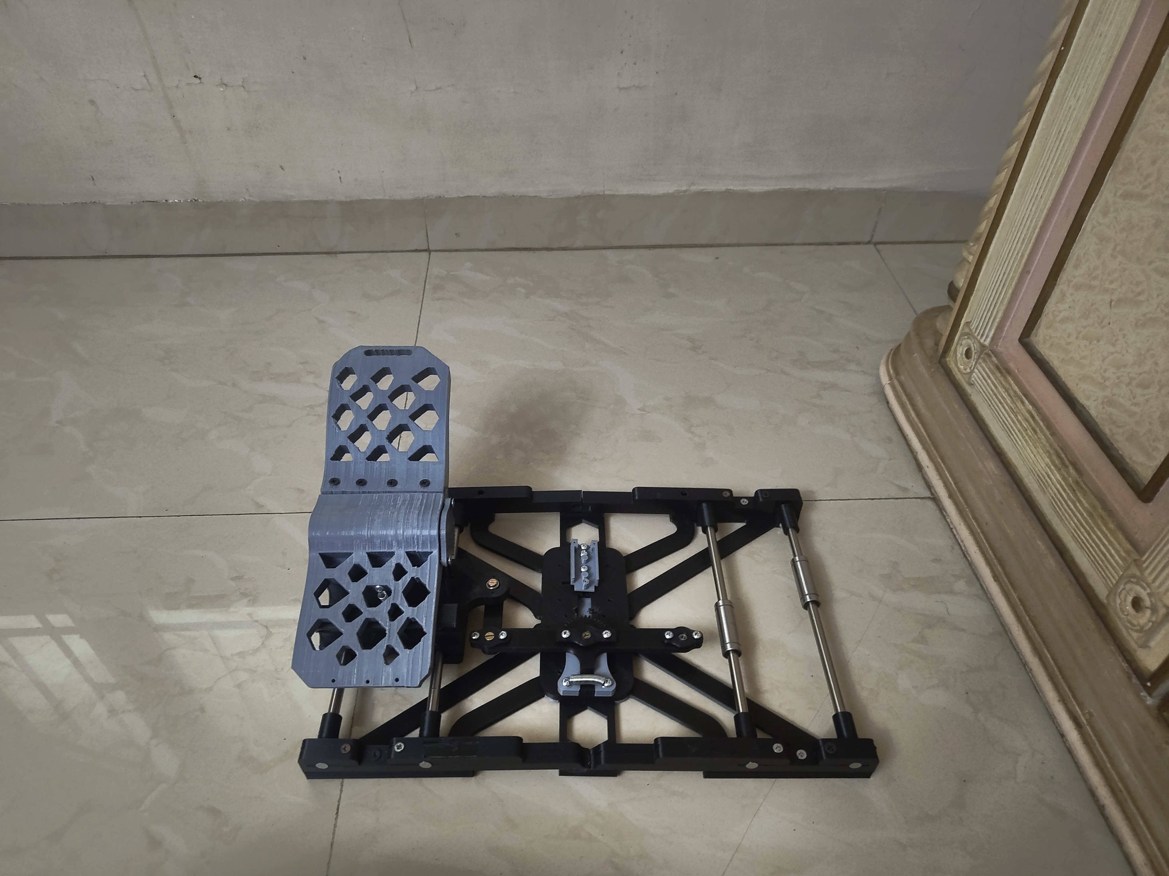
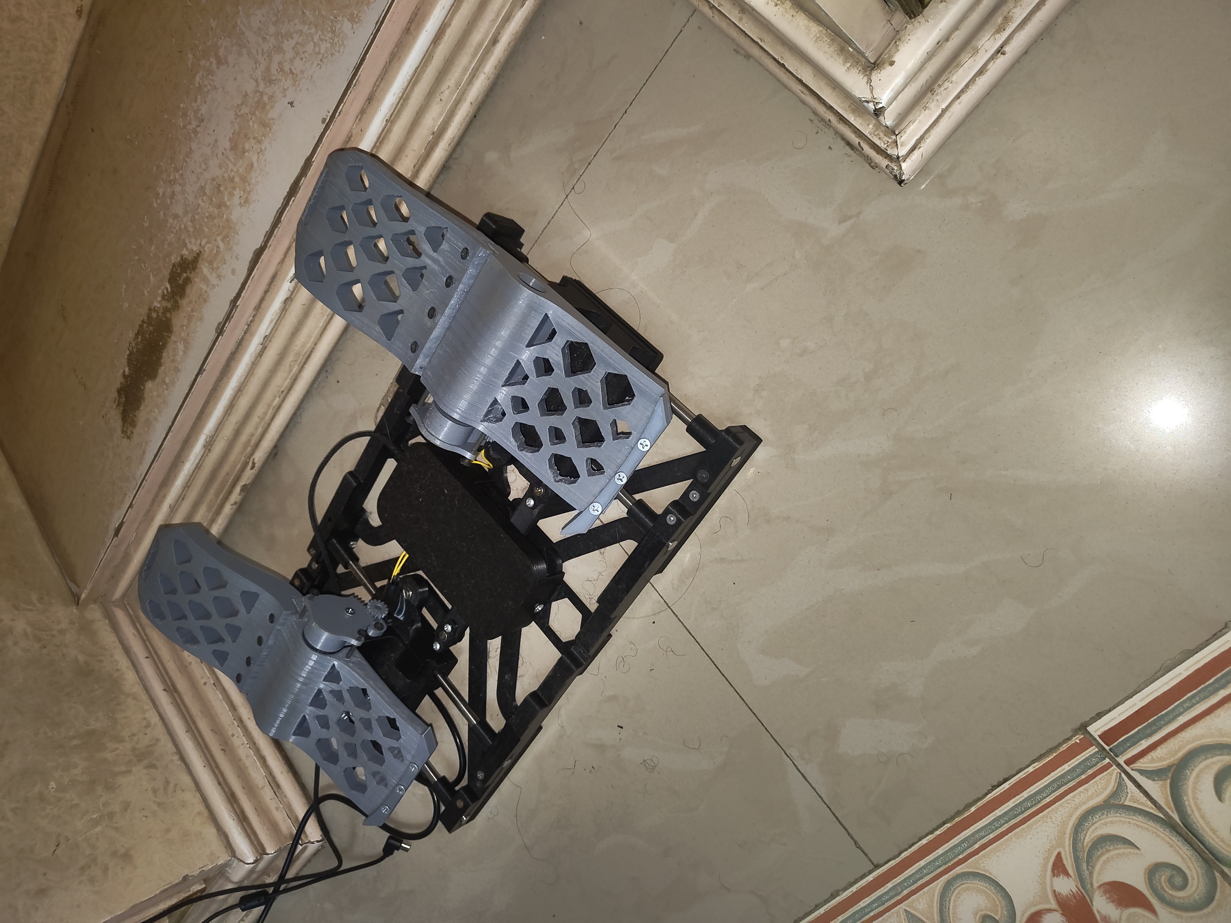
Project Red Phoenix — Rudder Pedals
This project died twice before a single part was printed. A fraudulent website. A commercial option with the wrong mechanics. Both times, building was the only answer left.
After finishing the throttle controller, the remaining gap in my simulator setup was rudder pedals — the foot controls that handle aircraft steering and braking. I had been using a workaround on my joystick as a substitute, but it was generating unreliable signals that were causing inconsistent control inputs. For months I had been blaming my own flying for errors that were actually the hardware's fault. I decided it was time to actually solve the problem.
The name of this project has a double meaning. RP stands literally for Rudder Pedals — and the name chosen was Red Phoenix, because RP fits both. Red Phoenix — because this project died before it started not once, but twice, and rose from the ashes both times. The name captures exactly how the project unfolded.
The completed Red Phoenix — both pedals and independent toe brakes fully assembled
▶
The First Death — A Fraudulent Website
My original plan was not to build rudder pedals at all. I had just come off six months of intensive work on the throttle controller, and honestly, the idea of immediately starting another full build was not appealing. I decided to simply buy a set this time.
I found a website that appeared to be selling flight simulation hardware. The price was within a range I was willing to consider. I placed the order, choosing cash on delivery — a decision that turned out to be the only thing that protected me from what came next.
The pedals never arrived. Days passed. Then weeks. No update, no tracking, no response. Eventually it became clear that the website was fraudulent — a fake storefront with no real product to deliver. Because I had chosen cash on delivery, I had never paid anything. The financial cost to me was zero. The only thing the scam cost me was the time I had spent waiting, hoping, and eventually accepting that nothing was coming.
The project was dead before it had started. Then it came back.
The Second Death — Wrong Mechanics
After the scam, I started looking at what other options existed. There was one commercially available set — a legitimate product from a known manufacturer — priced well above what I was prepared to spend. Before making any decision, I took the time to actually research how rudder pedals work on a real aircraft.
What I found was important. Real aircraft rudder pedals slide forward and backward. When the pilot pushes the left pedal forward, the aircraft yaws to the left. When the right pedal goes forward, the aircraft yaws right. This is a sliding, linear movement. In addition, each pedal has an independent toe brake — a small section at the top of the pedal that the pilot can press with the front of their foot to activate the brake on that specific wheel. The left toe brake controls the left main gear, the right toe brake controls the right main gear. This independent braking is how pilots steer on the ground, and it is especially critical for older aircraft types where it is the primary means of directional control during taxiing.
The VKB set did neither of these things correctly. Instead of sliding forward and backward, the pedals worked by pressing down — more like a car brake pedal than an aircraft rudder. There was also no independent toe braking on each side. For someone who cares deeply about how aircraft actually function, both of these things were disqualifying. I was being asked to pay a significant sum for something that was mechanically wrong in two fundamental ways. I rejected it.
The project was dead a second time. Then it came back again. The Red Phoenix rose.
Building It
With buying ruled out twice — once by fraud and once by inadequate design — building was the only remaining option. I could build my own set with the correct mechanics: proper sliding movement and independent toe braking on each side. And I could do it for less money than either option I had tried to purchase.
Unlike the throttle controller, which I had designed entirely from scratch, for the rudder pedals I took a different approach. I found an open-source design that another flight simulation enthusiast had shared publicly and decided to use it as my starting foundation. The decision was deliberate — I was not trying to prove I could design everything from zero. I was trying to get functional pedals as efficiently as possible. Using an existing design as a base and adapting it to my needs was the faster and more sensible path.
The main challenge throughout the build was the same printer tolerance issue I had dealt with on the throttle controller — parts consistently coming out slightly smaller than the design specified. With my own designs, I had been able to simply adjust dimensions in the model. With someone else's design, changing one dimension could break the fit of neighbouring parts. So I worked around it physically instead: drilling out holes that were too small, creating alternative mounting solutions where the original approach did not fit, and adapting each component until it worked correctly even where it did not look exactly as the original design had intended.
The Finished Result
The finished pedals use metal rails and ball bearings to give each pedal smooth, low-friction movement in the correct direction — sliding forward and backward, exactly as real aircraft rudder pedals do. Each foot has its own independent brake, exactly as real aircraft pedals do. Both things that made the commercial option unacceptable are present and functional in what I built for a fraction of that cost.
I completed the final assembly on my sixteenth birthday. The left toe brake currently has a loose wire that needs to be re-soldered — a known pending repair. Everything else is fully operational and has been used regularly since the build was completed.
What It Taught Me
The throttle controller had taught me that building from scratch is a viable response when the market fails you. The rudder pedals taught me something equally important: building from scratch is not always the right response. When a solid foundation already exists, the smarter move is often to take it, adapt it, and improve it — rather than spending months reinventing something that someone else has already solved well.
That distinction matters in business too. Innovation does not always mean creating something entirely new. Sometimes it means looking at what already exists, identifying exactly where it falls short, and building on top of it to make something better. That is what I did here — and the result was more functional, more affordable, and more correct than anything I could have bought. I intend to keep asking that question: where does something already exist that I can improve, and where does something need to be built from nothing?
Technical Notes — For Technical Readers [ tap to expand ]▸
The pedal geometry is based on a commercially available paid STL file set designed for flight simulation peripherals. The CAD files were used as provided without modification. All physical adaptation was performed during assembly: where printed tolerances were too tight, holes were drilled to achieve the correct clearance, and alternative fastening methods were used where the original design called for hardware that did not fit. The drill used for this purpose was an electric hair trimmer with a thin blade attachment.
Each pedal rides on two metal railings with metal ball bearings, providing smooth low-friction travel along the forward-backward axis consistent with how rudder pedals function on a real aircraft. Each pedal has its own independent toe brake, enabling differential braking on left and right sides independently. Filament: PLA.
In ProgressAviationDIY
DIY Head Tracking
The final piece of the custom cockpit. Hardware sourced. Build in progress.
I am currently building a head-tracking system for my simulator. The concept is straightforward: a small camera watches my head, and wherever I turn to look in the physical world, the view inside the cockpit follows in real time. In a realistic combat simulator, being able to look over your shoulder naturally — instead of pressing a button to pan a camera — changes the experience entirely. It brings a level of spatial awareness that is simply not possible any other way.
I am building this using a modified consumer camera that enthusiasts in the simulation community have found works well for this purpose. The hardware is already sourced. The build is in progress. When it is complete, every single piece of hardware in my simulator will have been built by me: the throttle controller, the rudder pedals, and the head tracker. Nothing bought off a shelf, nothing assembled from a kit — each one a custom build, started because something I needed did not exist at a price I was willing to pay.
05
Academics
AP Examinations
AP Calculus ABAwaiting Results
AP Calculus BCUpcoming
AP Computer Science AUpcoming
AP Business & Personal FinanceUpcoming
Pursuing AP examinations independently as part of a self-directed academic path that extends beyond the standard school curriculum.